(February, 2004)
Back in December, we won a dye laser head on eBay. (Our thanks to “teknogod4u”, who offered it.) It had a flashlamp and a dye cell in it, and looked interesting. The light from the flashlamp was coupled into the dye cell by a diffuse white reflector, and I wasn’t sure whether that would work at all well.
In the process of working on spark-gap triggering, which I’ve been doing during the last few weeks, I needed to test a triggering setup against our GP-14 spark gap; that provided the perfect excuse to get this head running. The GP-14 is good for 12 to 24 kV in air, a range that corresponded well with the testing I had in mind; and I had already mounted it on a capacitor (also acquired on eBay, perhaps a year ago) in anticipation of setting up a lamp-pumped dye laser.
Here is a schematic. It may not be exact, but it is close. (I worked it up in a hurry; it should show a resistor rather than an inductor. This conduction path charges the little starting capacitor, which improves the operation of the spark gap by helping it form a robust conduction channel quickly when it is triggered.)
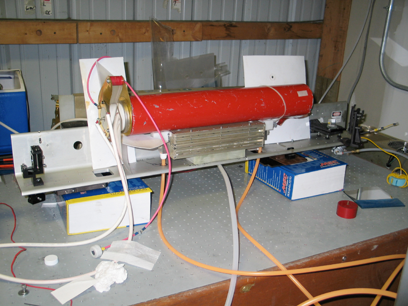
Here are an overview of the laser and a close-up of one end of the head. Sorry about the weird angle on the first photo; I stood where I could. The white rectangle that you can see in the first photo (it looks like a slightly bent sheet of extremely thick paper) is a piece of teflon that helps insulate the cathode lead of the lamp from the ground end of the capacitor — before each pulse, that lead is at the full positive supply voltage. (The structure that is barely visible at the back of the first photo, btw, is our Avco-Everett C5000 nitrogen laser head,) another eBay acquisition.
Yes, that’s a fuse clip on the end of the lamp. They work moderately well, though it’s preferable to coat them with silver-loaded conductive grease, if you have any, for better contact — strange things happen when you drop 10,000 amps through a fuse clip.
Note the little red “doorknob” cap across the GP-14; the mfr specifies that you want to push at least 10 amps through the gap when you trigger it, so that a righteous conduction channel will form; I find that a few hundred pf works well. That small a capacitance is also extremely fast, which is good because you want to overvolt the flashlamp as abruptly and thoroughly as you possibly can. (Yes, I know, it’s preferable to “simmer” the lamp at a few milliamps between shots, so that you don’t need to worry about this issue. It is, however, somewhat nontrivial to build a setup to do that, and I’ve opted for the simpler approach.)
The main storage capacitor is 0.1 microfarad, rated for up to 60 kV; I’m charging it to about 20.5 kV, so the stored electrical energy is about 21 joules. I did some informal measurements and found that the laser pulse is about 600 nsec long, which suggests that the electrical pulse is probably about 650 nsec long. (That’s actually longer than I’d hoped for, but it’s still fairly reasonable.) Given that pulsewidth, the power in the flashlamp during the pulse averages more than 32 MWE. The current isn’t really 10,000 amperes; but if we presume that the pulse is approximately sinusoidal and that the peak current occurs when the voltage is about 2/3 of the maximum, that puts the peak peak power at slightly over 45 MWE and the peak current at more than 3,300 amps.
For the moment, I’ve got an overcoated-aluminum-on-glass flat as the rear mirror, and what appears to be some sort of etalon serving as an output coupler. (The output coupler doesn’t show up in these photos, but if you look carefully you’ll see the aluminum max-ref near the right edge of the first picture, just below center, on a black metal mount.)
The diffuse reflector, btw, was not viable, and I ended up close-coupling the lamp and the dye cell the way I always do, which is by wrapping aluminum foil around them. (I have never bothered with ellipsoidal reflectors, having decided very early on that they weren’t worth the trouble. Aluminum foil works quite well, and is much easier to deal with. Just remember to keep it away from the high voltage. I always keep it shiny side in, and I can’t tell you whether that’s crucial because I haven’t ever bothered to try it with the dull side in.)
I used a front-surface mirror to reflect the beam up to the wall, so the spot in the next photo is maybe 8 or 10 feet from the output coupler. The dye solution was Rhodamine 6G in 91% isopropanol; I took the first picture with the camera white-balance set to “Cloudy”, to get moderately reasonable color rendition of the laser output, at the expense of making the wall look somewhat greenish. (The room lights were on, and they’re fluorescents...) The second picture was taken without room lights, and with the white-balance set (by mistake) to “Auto”.
As far as I can tell, these are to the same scale; but in the first shot the mirrors are poorly aligned, and in the second shot I have them aligned much better. Note the differences in spot size and shape. (You can tell that the alignment is better in the shot on the right by the fact that the center spot is a lot smaller and a lot closer to round. It is also intensely bright, even to the eye.)
Inasmuch as there’s no real sense of scale here, I should
note that these photos show an area of wall that is
something like 12 or 14 inches across. I haven’t made any
attempt to minimize the divergence or select a single
transverse mode — haven’t done anything fancy at all
yet, in fact. This is just an extremely informal testing setup.
It should be clear that we don’t have anything like the
simple mode structure you see with HeNe lasers. There are
several reasons for this, two of which are A) that this is a
long dye cell with reflective walls, and B) that I do not have
a carefully designed cavity around it. Perhaps some day I will
have a chance to acquire an output coupler with the right
curvature, and some iris diaphragms... in the meanwhile,
however, I’ll take what I can get.
(23 February, 2004)
This evening, I tried a Littrow prism as the rear reflector.
I found it slightly harder to threshold the laser, but it
was interesting enough to be worth playing with. I could
almost swear that I saw laser-speckle in the beam (see the
photos), but I don’t have an easy way of checking the
coherence length, so I can’t swear to it. (Dye lasers
aren’t particularly coherent unless you have a dispersive
element in the cavity to tune them and narrow the output,
so they don’t generally exhibit speckle.)
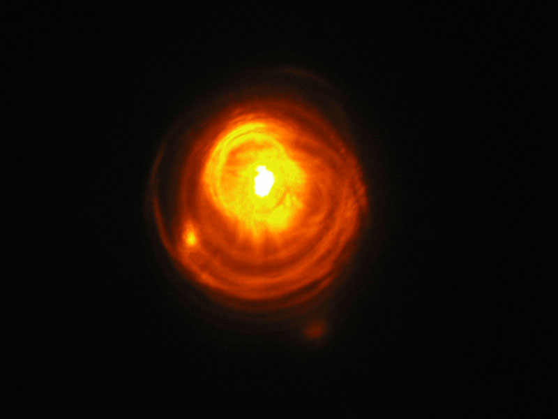
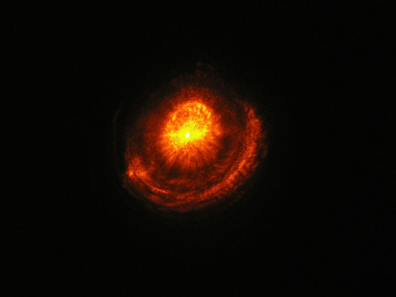
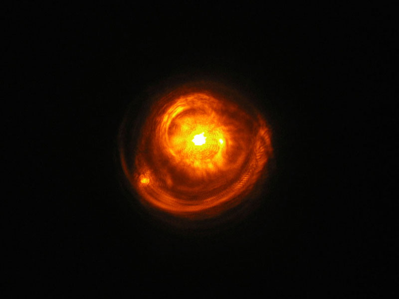
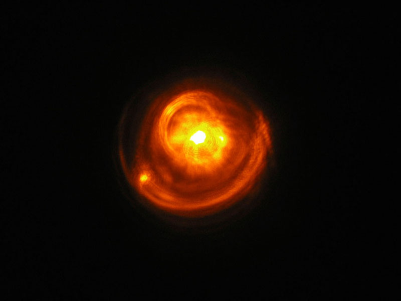
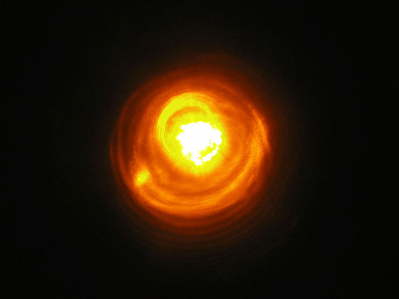
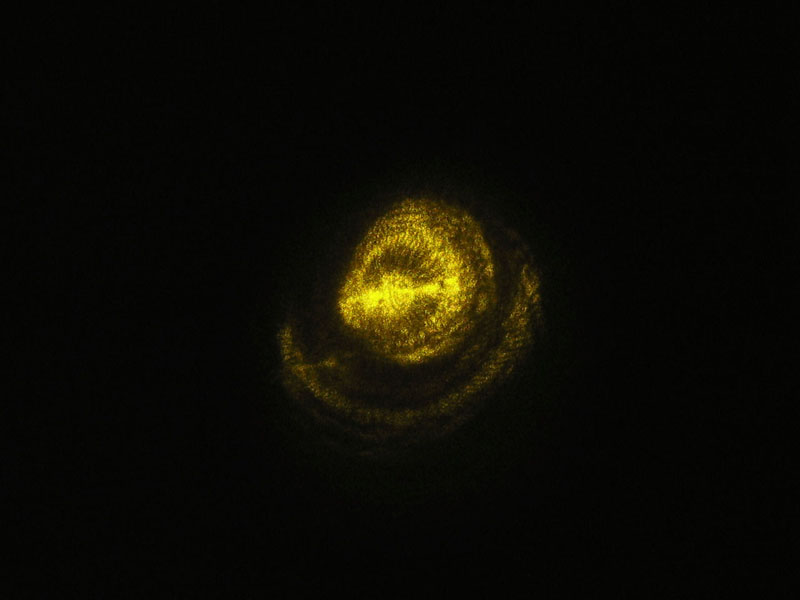
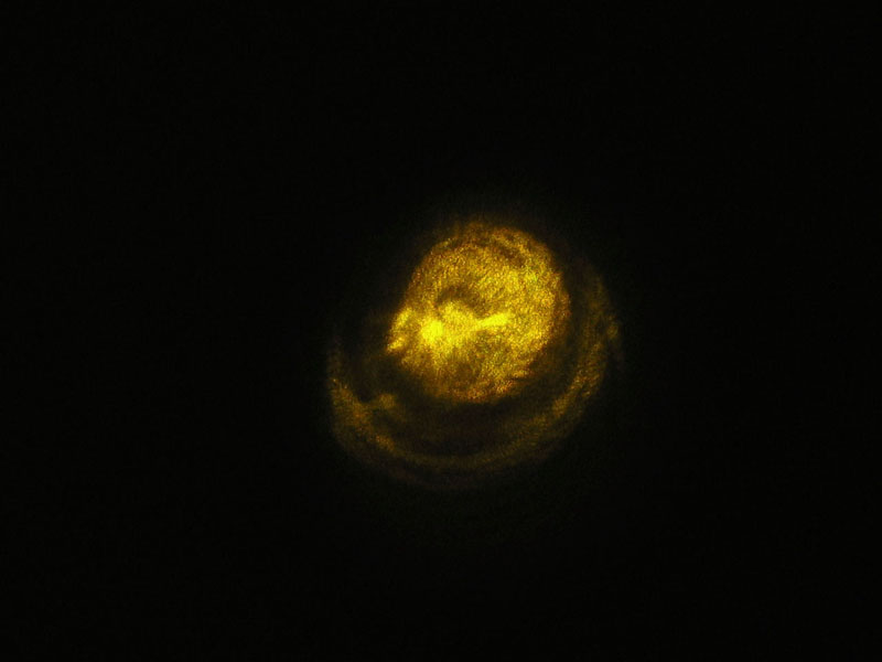
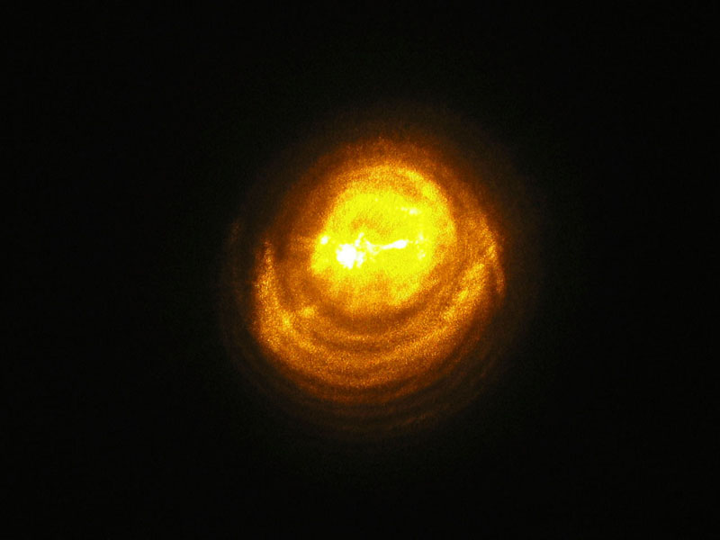
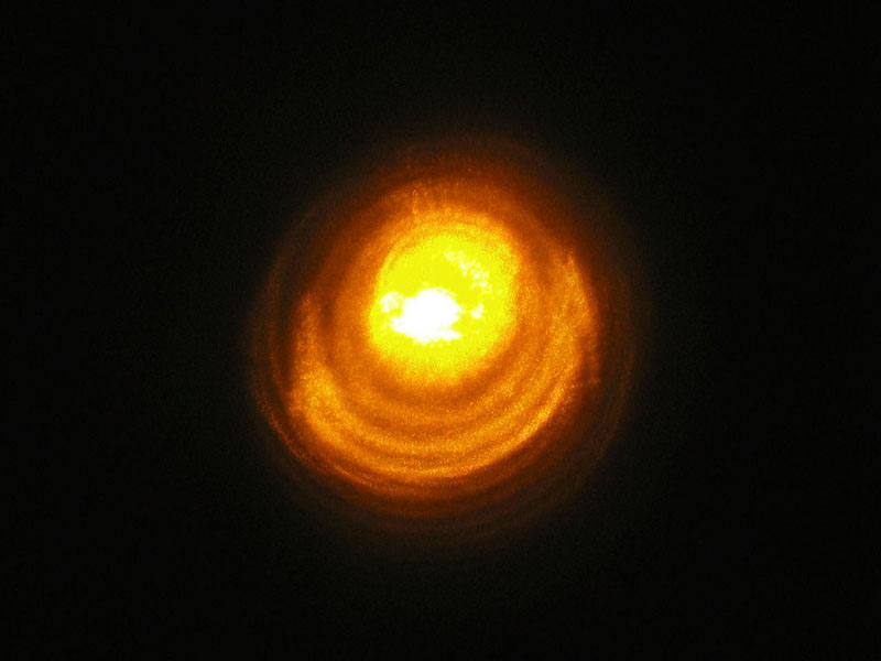
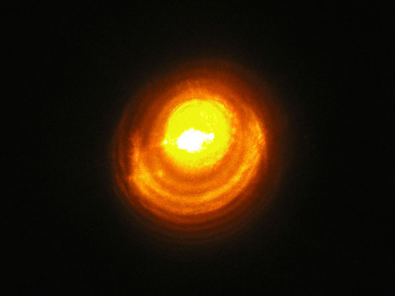
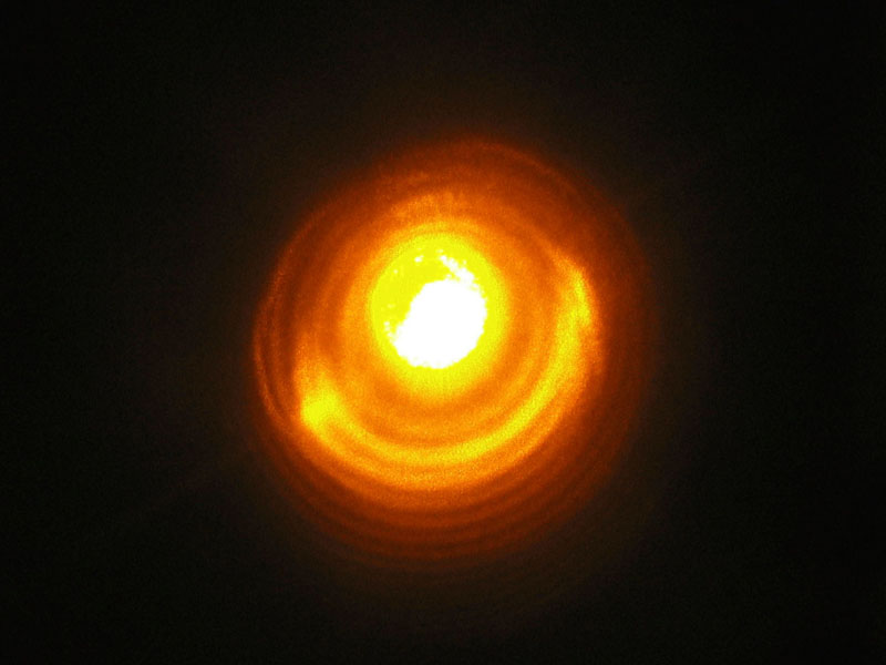
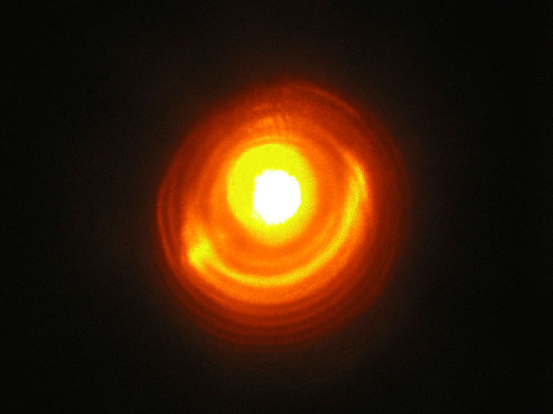
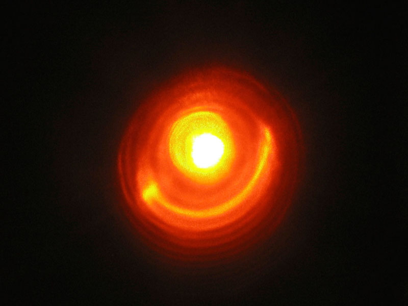
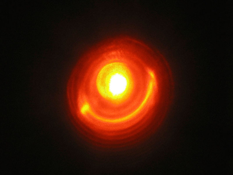
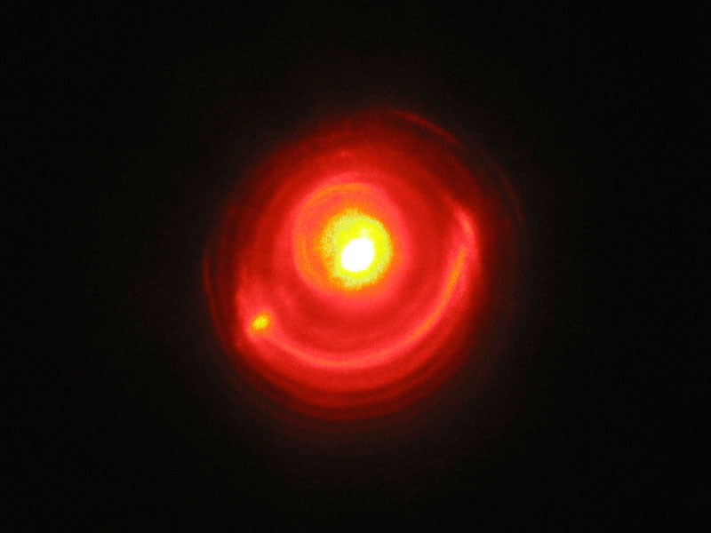
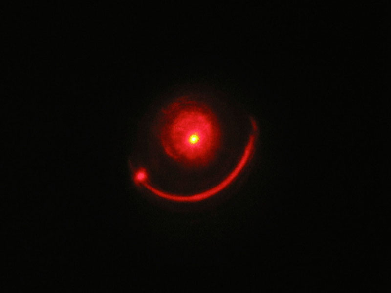
Here, anyway, are four photos. The last one is taken at
about 23.3 kV, I think the third one is at 20.5 and I’m not
really sure about the first two, though there’s some chance
that the first one was taken at about 19.8. (There is a
certain amount of shot-to-shot variation, even at a given
voltage.) It’s possible, btw, that only the first two were
taken with the Littrow prism as the max-ref rear mirror —
the other two don’t seem to show the graininess that I
recall, and I know I swapped mirrors several times during
the course of the evening yesterday.
I have to say that these look to me like a sequence
showing a flare-up of the star in the middle of the
Zarf’s-Ear Nebula...
(24 February, 2004)
I put an equilateral dispersion prism (made of SF2 glass)
into the cavity this evening, reverted to the aluminum
max-ref, and tuned the laser. It worked reasonably well —
here’s a photographic tuning curve of the Rhodamine 6G dye
solution I’m using at the moment:
These were taken at about 23.3 kV; they should be at the
same scale as the previous ones, but I’ve made the
thumbnails very small so they’ll fit better on the page and
so you can see the color differences more easily. Just as
with the previous images, btw, if you want the original bits
(actually a 1280x960 crop from the original JPEG), just
click the small image and then change “.8c.” in
the resulting filename to “.12c.”.
There appears to be a gap between the second and third photos;
I’m not really sure what that’s about, and I may
take another look at some point. The best way to check, I
think, will be to get a spectrometer on the thing and make a
“real” tuning curve, with wavelength and relative
(or even absolute) pulse energy. Before I can do that, however,
I’ll probably have to build a more stable version of this
laser, maybe on its own little table. (I am tempted to build a
“soda-can” optical table for this, but I don’t
have the patience to drill and tap a zillion 1/4-20 holes in a
sheet of aluminum; and I hardly ever drink soda, so I’d
have to enlist the help of lots of friends to get the cans.)
I should also note that the yellow regions in the last few
images are camera artifacts — the beam was intense enough
to “blow out” the sensor, even at that end of the
tuning range.
Here is an overview of the tuning setup, such as it is — I
just sat the prism on something and moved the mirror into the
new beampath, then tweaked the mirror until I got lasing again.
(Remember, I am using a HeNe to align this setup, and 633 nm
is well outside the tuning range of R6G, so the laser is
guaranteed not to work after I line everything up.)
(26 February, 2004)
I have taken the laser down so that I can mount it on a
piece of extruded aluminum “L” that used to be
the optical rail in a pulsed YAG laser. I suspect that it will
be considerably more stable when everything is firmly attached.
I’m considering taking one of the reflections off the prism
as the output beam, and using two “max-ref” mirrors.
That won’t optimize the output power, but it may optimize the
tuning range. I’ve begun this rebuild, and should have the
laser running again within a few days. (If I’m really lucky,
I’ll have it running tomorrow, Saturday, the 28th.)
(28/29 February, 2004)
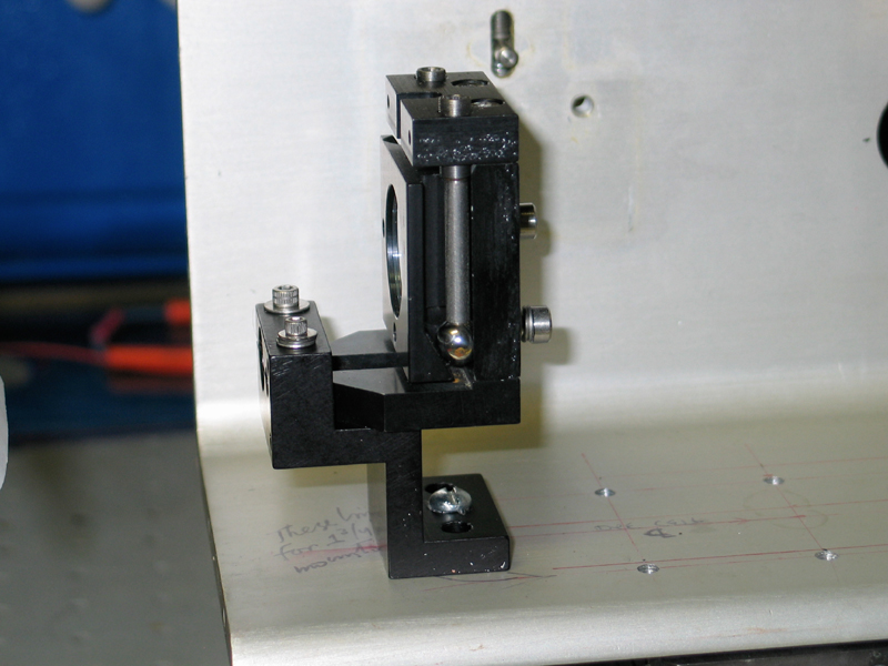
Got the head mounted on the rail; kluged a stand for a
mirror mount that’s designed for 1.25" height (the dye
cell center is just under 2.5" off the deck); added a
mount for the prism; and set up the max ref rear mirror
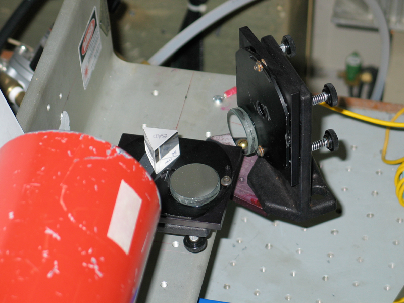
on a cantilever. Here’s an overview, with a close-in
view of the kluged stand and its mount, and a moderate
close-up of the tuning section:
You can disregard the mirror next to the prism — it
was already attached to the mount, and I just left it
in place for now. I’ll probably remove it later, so it
doesn’t collect too much dust.
I’m having trouble with the alignment right now, and
I’m not getting the tuning range I want; but I hope
to resolve that within a few days, and I’ll be putting
the output through our little Oriel monochromator to
collect tuning info. The wavelengths will be approximate,
but I can at least calibrate it against a HeNe, which is
a start. (It actually seems fairly accurate.)
(Note, added 2004 March 08)
I put a small iris diaphragm in, near the tuner, as a
field stop. This seems to help a little, but I think
I’ll need to put another one at the OC end.
(It’s on order.) These should have two effects:
first, they should keep the beam restricted more or less
to the center of the dye cell, which should discourage
the “Zarf’s-Ear Nebula” effect. (I
know, it’s pretty, but it’s not very
efficient.) Second, by keeping the beam running more or
less down the enter of the dye cell, the stops should
discourage walkoff caused by the tuner. (The laser, no
surprise, runs best at wavelengths where the dye has
high gain. As I attempt to tune toward the end of the
range, lasing will occur at an angle through the cell,
which detunes it, unless I forcibly prevent it from
doing so.)
For other “photographic tuning curves”, please see
the 4-Methyl-Umbelliferone page and my page about
a simple nitrogen-laser-pumped tunable dye laser.
Email: a@b.com, where you can replace b with joss and a
with my first name (just jon, only 3 letters, no “h”).
Phone: +1 240 604 4495.
Last modified: Fri Jun 15 23:03:39 EDT 2013
The Littrow Prism
Tuning:

Next Steps
Riding the Rails
the Joss Research Institute
19 Main St.
Laurel MD 20707-4303 USA