[Started on April 8, 2011.]
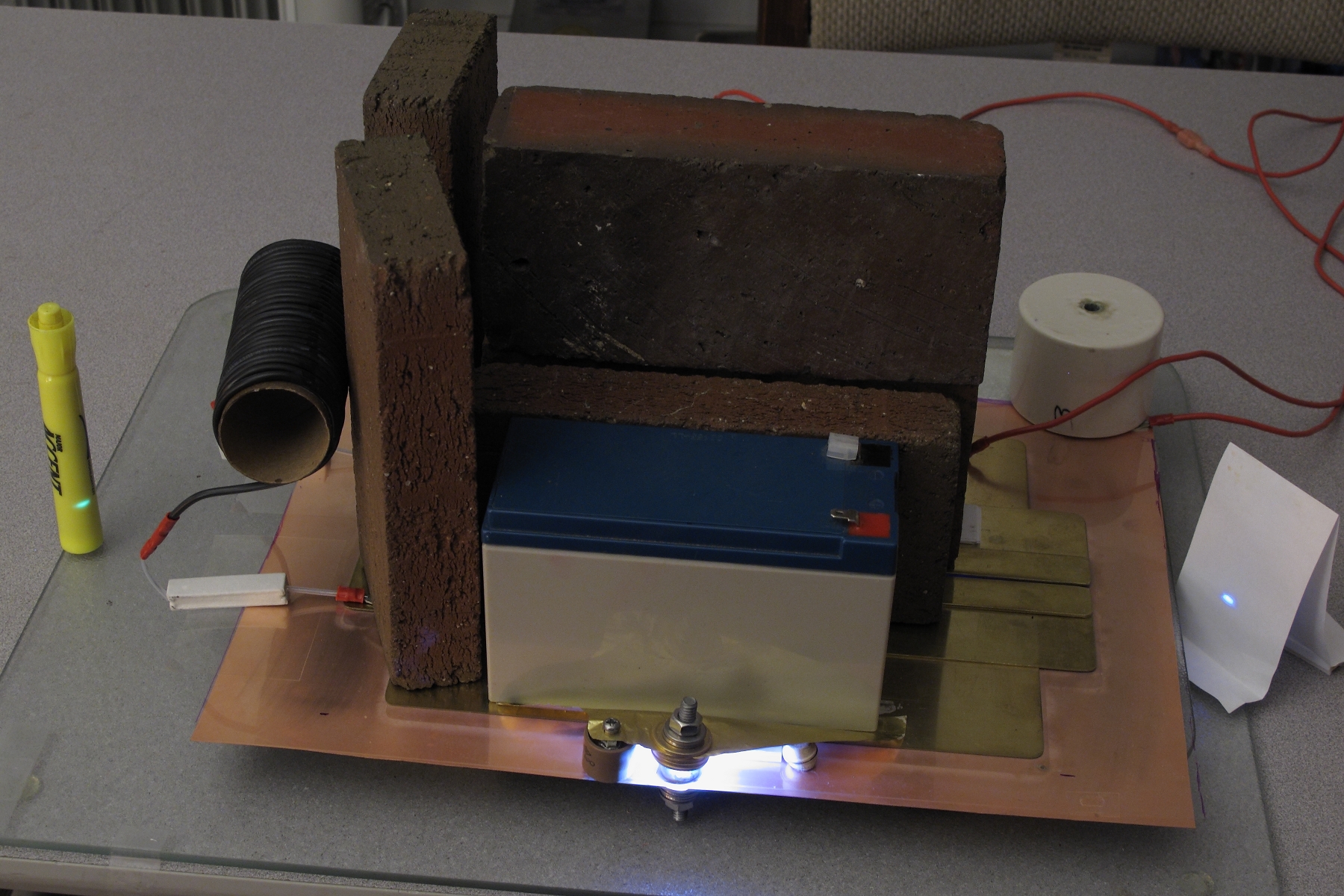
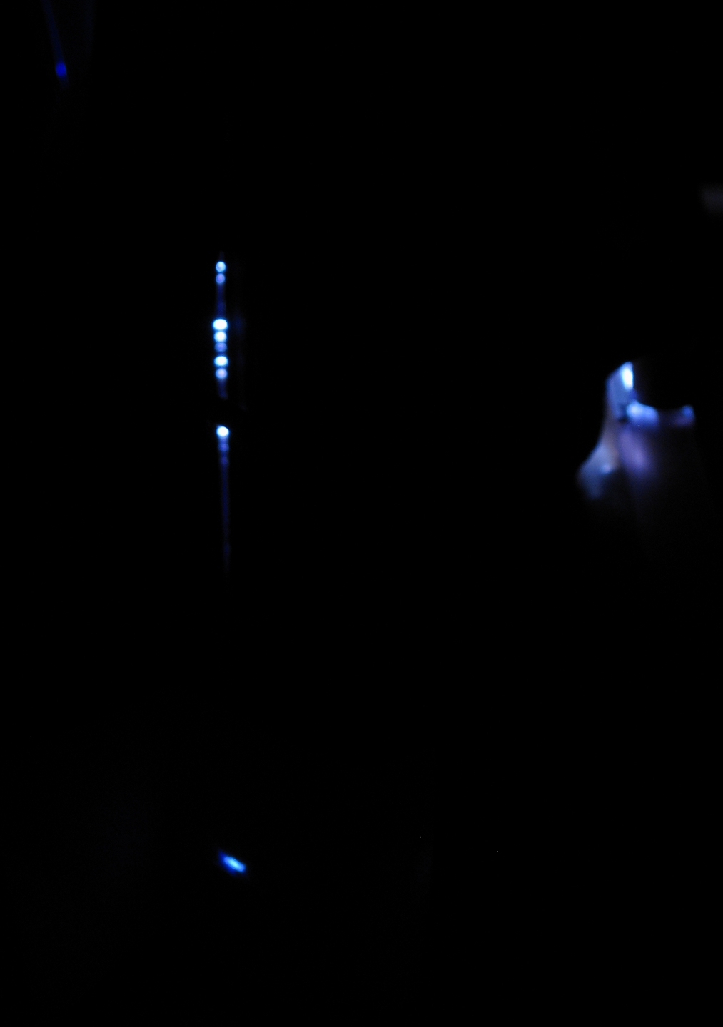
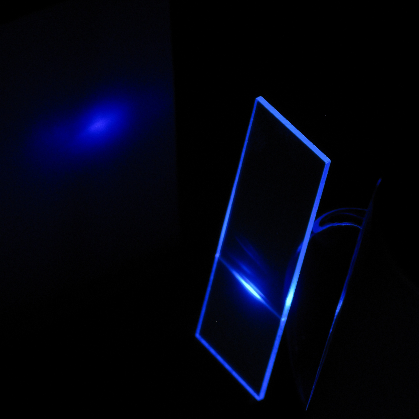
This photo shows a version of the laser in operation.
The output is not visible to the eye; the fluorescent
objects on the left and right indicate the presence of
the beams. (Because there are no mirrors, the laser
produces two.)
Amateurs have been building lasers since fairly shortly after the laser was invented. Several laser projects even appeared in the late (and much lamented) Amateur Scientist column in Scientific American, which is now, fortunately, available in its entirety on CD-ROM. There are also various pages on the Web that provide information about DIY lasers of various sorts, and I provide links to some of them at the end of this page.
Unfortunately, I see quite a few videos on YouTube in which someone has bought a little laser module and hooked it up to a battery; they then proudly claim that they have built a laser. That’s pretty sad, especially when almost any of them actually could have built a laser. This page is for you if you really want to build a laser, and not just buy one.
The lasers I describe here are TEA nitrogen lasers. (TEA stands for Transversely Excited, Atmospheric [pressure].) That is, they do not involve either vacuum or compression. The basic design is sufficiently straightforward that it can be built by a high school student who is particularly interested, or possibly even a middle school student who is truly determined. A laser of this type that is constructed with some care and is properly adjusted should put out more than enough power to drive a small dye laser, as you can see in the addendum near the end of the page. There is also an upgrade path, which can become quite challenging.
Before we get any further along, we need some safety
information and a disclaimer.
These lasers use high voltages, and capacitors that can store lethal amounts of energy. They put out invisible ultraviolet light that can damage your eyes and skin. It is extremely important to take adequate safety precautions and use appropriate safety equipment with any laser; and it is crucially important with lasers that involve high voltages and/or produce invisible beams!
In addition, these designs use open spark gaps, which will damage your hearing if you do not use adequate ear protection. I strongly suggest that you acquire and use at least a pair of sound-protection earmuffs of the type used by shooters at rifle and pistol ranges; they look about like this:
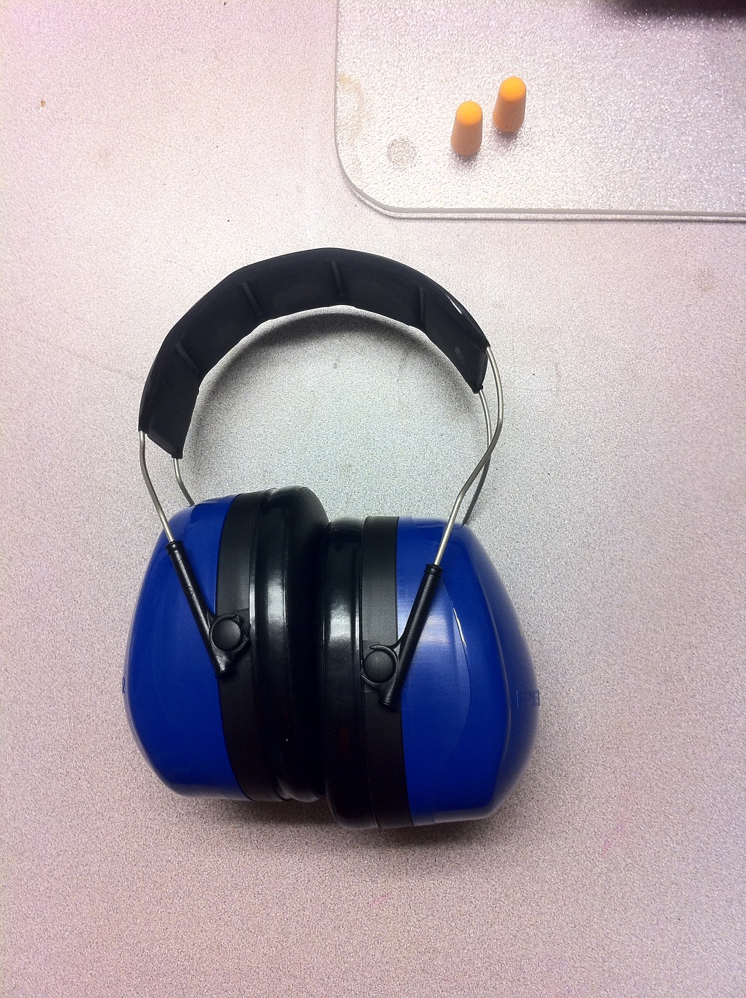
(These cost me $35, and they are definitely worth it.)
Earplugs can also help, but by themselves are probably not sufficient unless they decrease the volume by about 33 db and you put them in correctly; I suspect that only special ones that are made to fit your own ears are really good enough.
If you are not using enough hearing protection, you will
probably get a nasty headache if you run the laser for a
while. Take that as a warning, and get better protection!
You can make a new spark gap, and you can make a new
laser; but you cannot make new eyes, ears, or fingers.
In the process of working up this page I built several versions of the laser, increasing the complexity each time I revised it. Here (Video 1a) is an informal video that begins with a simple laser, similar to the first version I present on this page, though with a different spark gap design. The laser was not very sophisticated, but as you can see in the video, it worked. (In retrospect, though, I will point out that in the later part of the video it is firing too often.) Here (Video 1b) is a video in which I assemble and operate a somewhat more sophisticated version. [Note, I did not compress this video, and the filesize is >40 MB.]
It is important to note two things about this. The first is that building a simple machine provides you with experience that helps you build more advanced versions. (No surprise there, I trust.)
The second is that this first simple machine can easily evolve, in stages, into a considerably more advanced laser with far better performance. You don’t have to throw it away and start again from scratch, because you can create a more advanced version by modifying it, as I do in the course of the first video.
Of course, if you want to start over again, nothing prevents you from doing so. The version that you see in (for example) Figures 22 and 23 was a complete rebuild, as is the one in Video 1b. That’s another handy thing about these lasers: after you have built several, you will probably find that it takes you only an hour or two. (Don’t expect your first few to be that quick, though; it does take practice.)
Although there are, fortunately, lots of good ways to
build TEA nitrogen lasers, there are also lots of bad
ways. It is particularly important to remember that if
you try something and it doesn’t work, you need to
document it carefully anyway, because you will almost
certainly need the information later on, in order to
figure out something that does work. You will
probably also need the information in order to avoid
repeating the same error[s]. It is a great relief (and
sometimes a large surprise) to return to your notes,
possibly months or years later, and find something you
did that you may have forgotten about, and to have at
least some of the information you need in order to
understand how it worked ...or didn’t.
In order to build one of these, you will need the following things:
You want your sheet of shim stock, or whatever you end
up using, to be smooth and flat; if it is buckled or
wrinkled, it won’t make good contact with the
dielectric. However, a small amount of buckling or
wrinkling that is near the edge, as long as it is well
away from the upper capacitor plates, should not be a
problem.
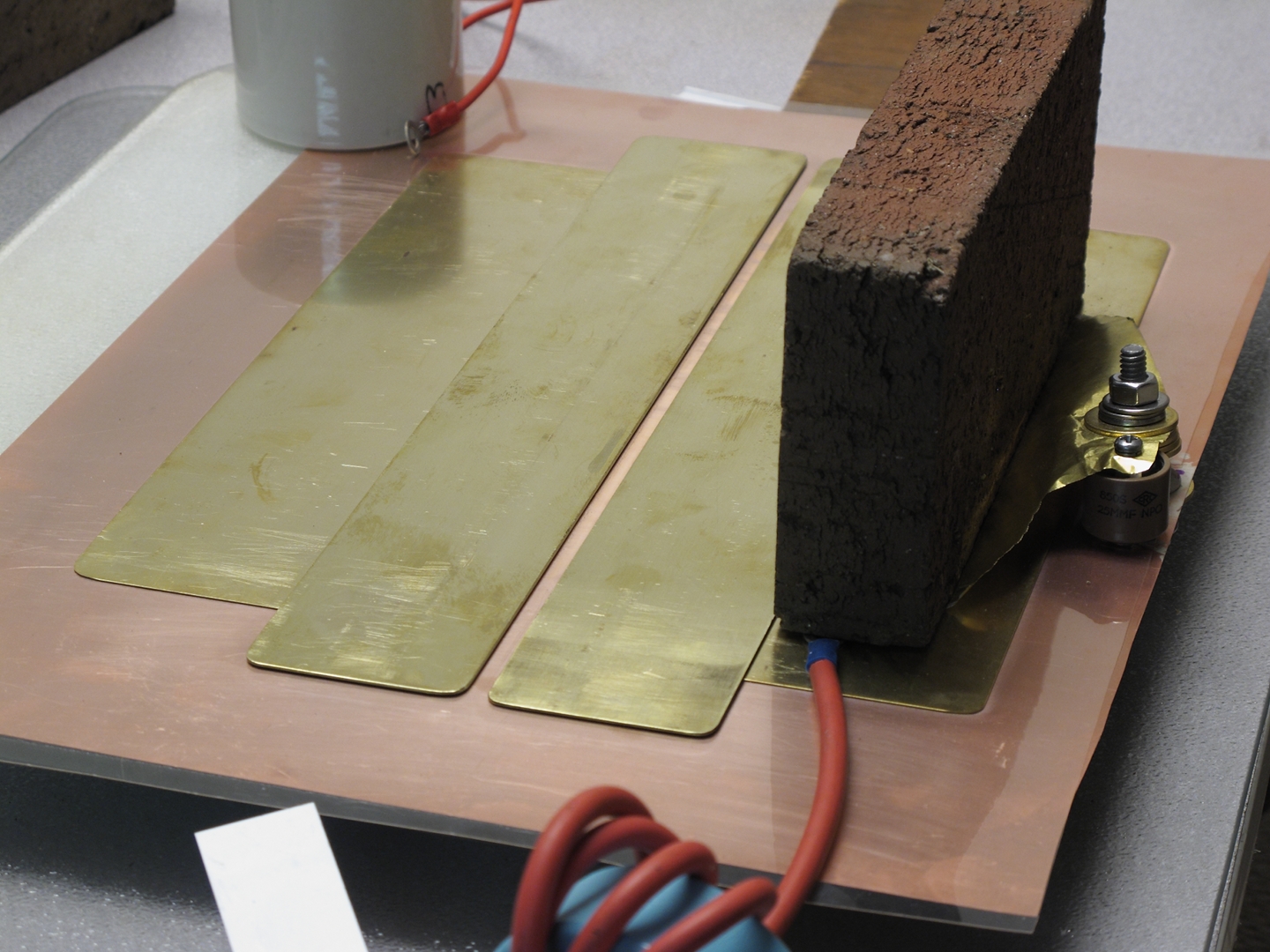
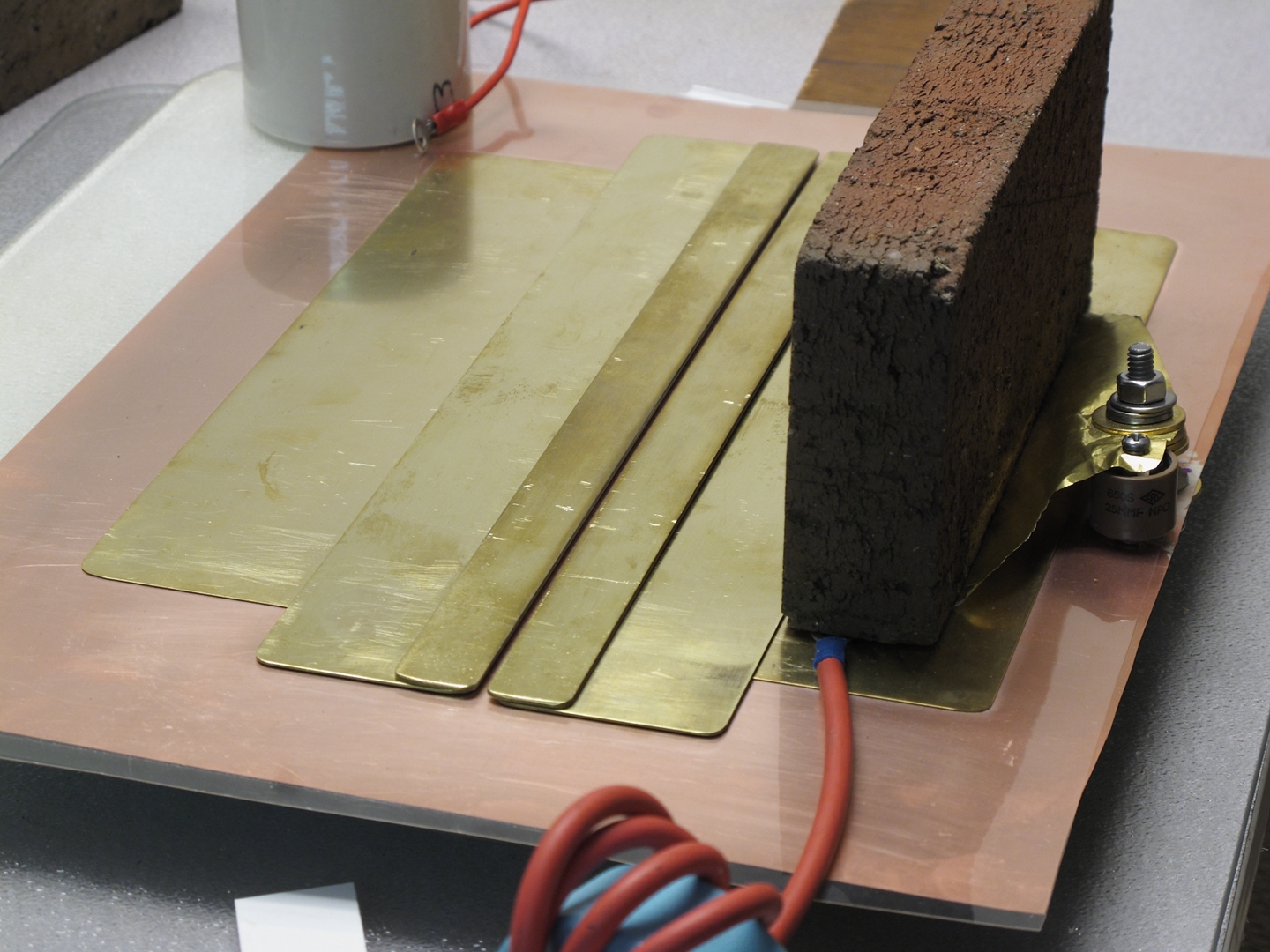
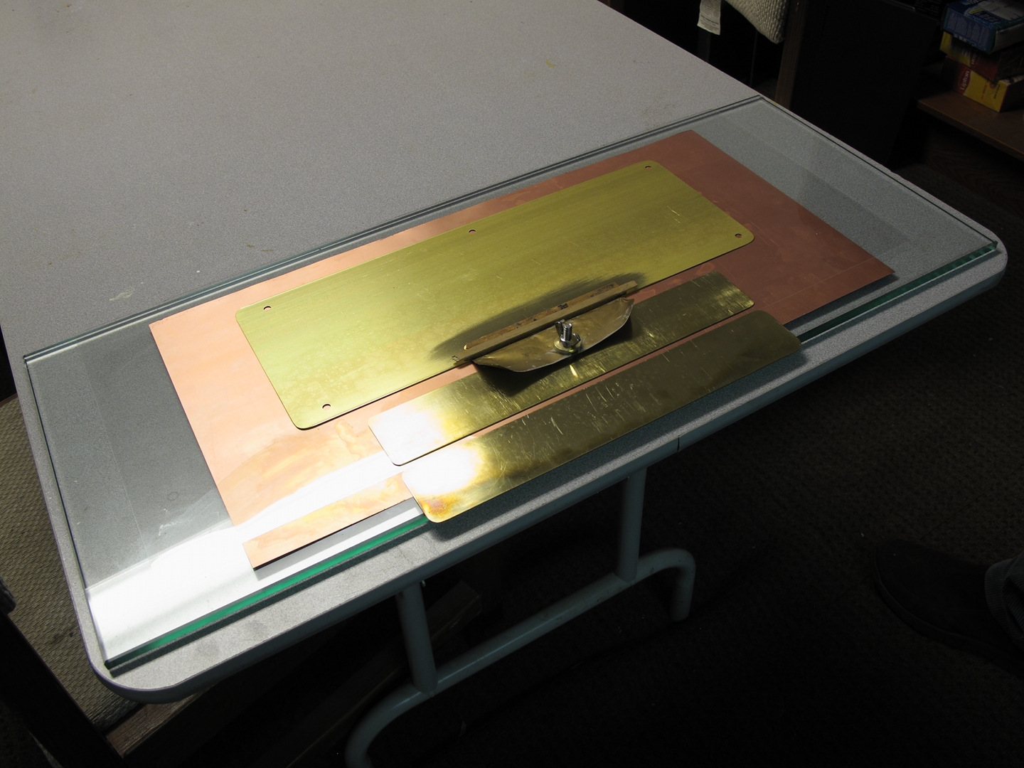
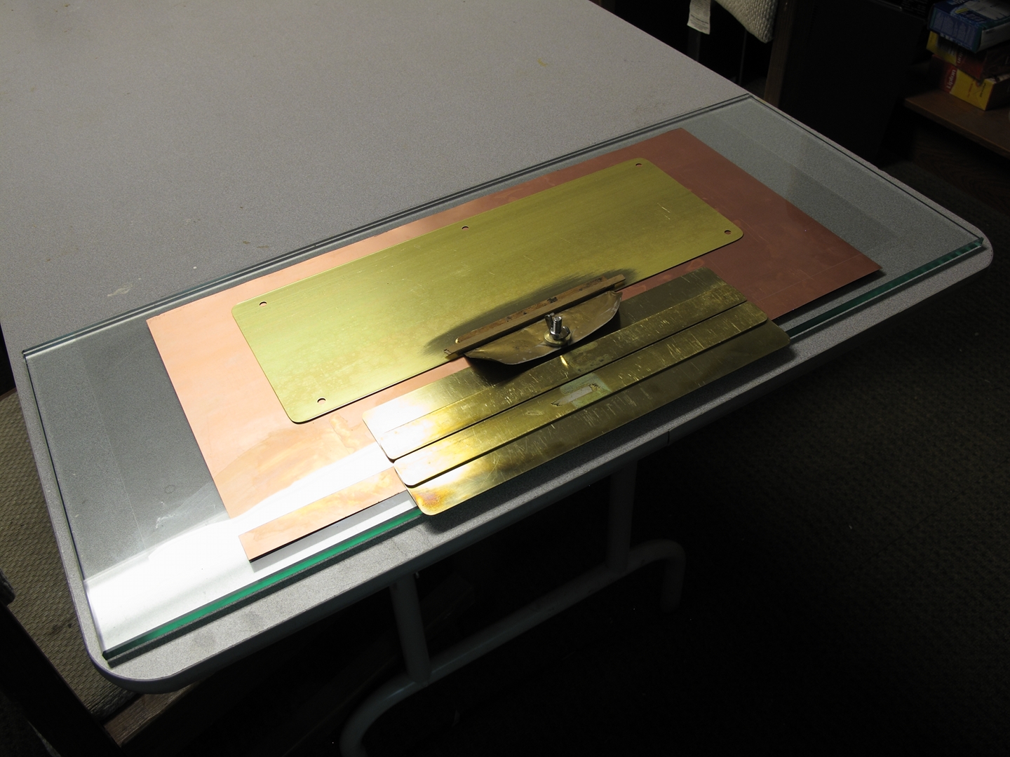
For the upper plates I used small sheets of brass (2" x
12") that I got at the hobby shop. In the first version,
these also serve as the electrodes of the laser. They
are available in various thicknesses; I found 32 mils or
even 64 mils to be convenient, for reasons I’ll
get into when I describe some improvements.
These lugnut covers are available at truck stops, and
they are not very expensive, but I decided to use a
different design here, partly to find out how well it
would work and partly because the parts that I needed
for it are available at hardware stores.
I use crimp connectors, but you can avoid them if you
want or need to.
One unusual item that I have found helpful is a special
glue that is electrically conductive. The version I used
to buy has been replaced, and I have not tested the new
version yet, but I expect it to work just as well. I get
this glue from the
Electron Microscopy Sciences division of emsdiasum.com.
(The link is to their catalog page for adhesives; look
for the word “Conductive” a little less than
1/3 of the way down the page if you want to see all of
the relevant offerings; the material I will be using in
the future, when I have used up the bottle I currently
have is “Silver Conductive Adhesive 503”.)
Strictly speaking, conductive glue is not necessary; but
it does help avoid sparking where close contact is
needed. You can see it, for example, under the back end
of the spark gap in the overview photo of the laser
where I mention replacing the resistors with an
inductor, just before the first photo that shows the
output.
You will also need some weights, to hold things down. It
is important to get the capacitor plates into good
contact with the dielectric and the dielectric into good
contact with the baseplate, because air will decrease
the amount of capacitance; because of that, it also
decreases the amount of energy that the capacitors can
store at a given voltage, and interferes with the
performance of the laser. In the more complex versions
of the design you also need to insure good contact
between the electrodes and the capacitor plates, and you
need to hold the electrodes in place so they don’t
slide around. I have used a wide variety of objects for
this purpose, several of which you can see in the
photos: bricks, worn-out sealed-cell batteries from a
UPS, pieces of scrap metal, and so on. One of my weights
is a spice jar filled with small nuts and bolts. (Jarrod
Kinsey has sometimes used cans or jars that he has
filled with pennies; I like nonconducting weights,
because if you accidentally touch one you won’t
get shocked, so I would use glass or plastic jars,
rather than metal cans.)
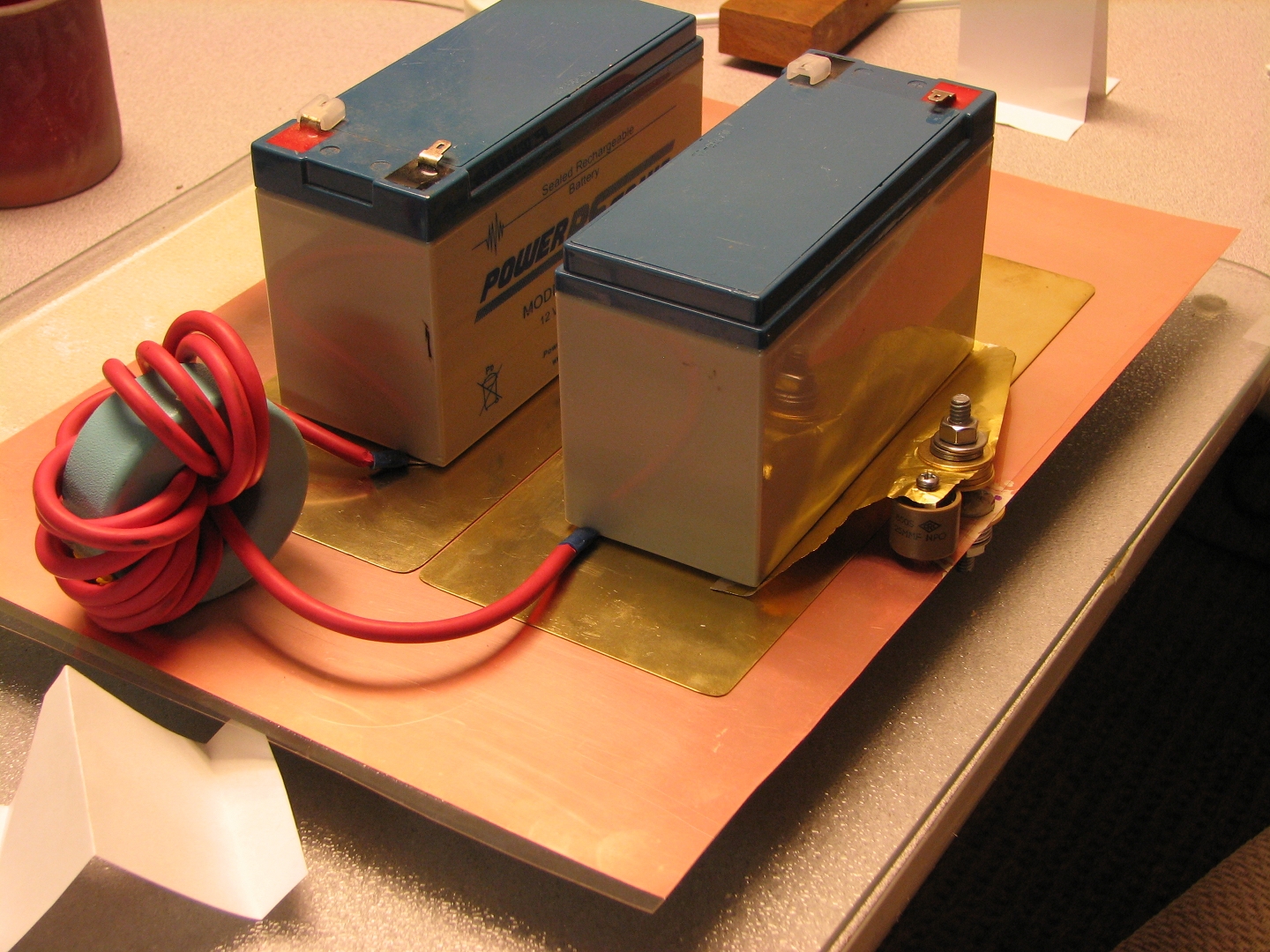
For ease and convenience, I have taken the power supply
out of an old electronic air cleaner. Here is the air
cleaner before I disassembled it:
This is what the right side looked like with the cover
off:
The power supply consists of a transformer and a small
circuit board. Here it is on its new base, with a
switch so I can control it:
(Please note that this is just a temporary
setup. Although the high voltages are insulated it is
not safe to have line voltage exposed as it is here, and
I will eventually enclose this supply in a
well-ventilated insulating box.)
I made a voltage divider by putting a 100-million-ohm
high-voltage resistor in series with an ordinary
10,000-ohm resistor, and I used the divider to measure
the output voltage from this supply. The schematic
diagram on the bottom of the case says that the supply
puts out 5500 VDC at 0.3 milliamps, but that turns out
to be a description of one polarity, not both: I
measured roughly 5980 volts on the positive terminal and
roughly 6390 volts on the negative terminal, for a total
of over 12 kV. This is the open-circuit voltage; when
the supply is providing current to a load, the voltage
is lower.
I have been using two bases for this laser; both of them
are glass, and I got both at thrift stores. (I used
glass because the lower electrical plate of the laser is
at high voltage, and I wanted to keep it isolated from
the table. In addition, glass is generally flat, which
is important.) The glass pieces I found are intended for
use in the kitchen, and they have pebbly top surfaces; I
decided to live with that, but if you find one that has
an extremely flat bottom surface you may want to turn it
over and use the flat surface as the top. Alternatively,
a plain piece of window glass will work, but you should
make sure that the edges are not sharp. If you prefer to
avoid glass, various kinds of plastic sheet can be used
to insulate the high voltage from the bench or table;
just be certain that the upper surface is clean and
flat.
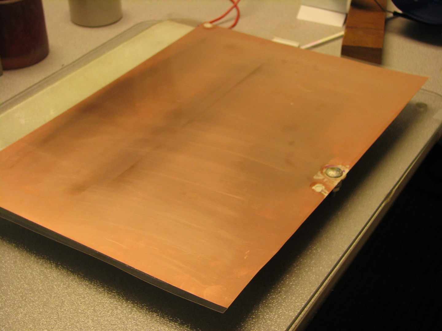
I used a piece of single-sided circuit board as the
baseplane of the laser (it would ordinarily be the
ground plane, but because of the way the power supply is
configured, it is definitely not at ground potential),
largely because I have several pieces, acquired on eBay
some time ago, that are of an appropriate size. Also,
although it is quite thin, this material is just stiff
enough that the pebbly surface of the glass underneath
it is not a problem. (The board is so thin, in fact,
that it can be cut with a pair of scissors. I
don’t recommend doing that if you have a tool that
is better suited to the job, however, because cutting
circuit board isn’t a very nice thing to do to
your scissors.)
Brass shim stock is a good alternative that you can get
at some hardware stores, and also on eBay. It works at
least as well as the circuit board. Shim that is 0.003"
or 0.004" thick should be suitable; if it is any thicker
it starts to become more difficult to cut, so you may
want to obtain a pair of tinsnips if you don’t
already have one.
The next step is to find a piece of plastic that can
serve as a dielectric. I had originally intended to use
overhead projection transparencies, but then I went to
an office supply store and priced them: $40 for 100
sheets. I eventually found some at a thrift store for a
much more bearable price, but they are only 0.004"
thick, and that isn’t enough to handle the full
output of the power supply, so I went to the hobby shop
and bought some styrene sheets that are 0.010" thick and
about 18" long. These work quite well, but it is
important to remember to get the long size if you are
using long electrodes: the brass sheets that I used as
the upper plates of the capacitors in my initial
versions of the laser are 12 inches long, which meant
that I needed a dielectric sheet at least 13 inches
long, and preferably longer. High voltage will jump
across insulators if it can, and you need to provide a
margin of more than half an inch all the way around the
capacitors. Likewise, when I use brass sheets that are
4" x 10" (another size that I can get at the hobby shop)
it is easier to deal with the length, but I need to use
a piece of plastic that is well over 8½ inches wide, and
because of the spark gap, which I have positioned at one
edge of the laser, I really need at least 10 inches of
width.
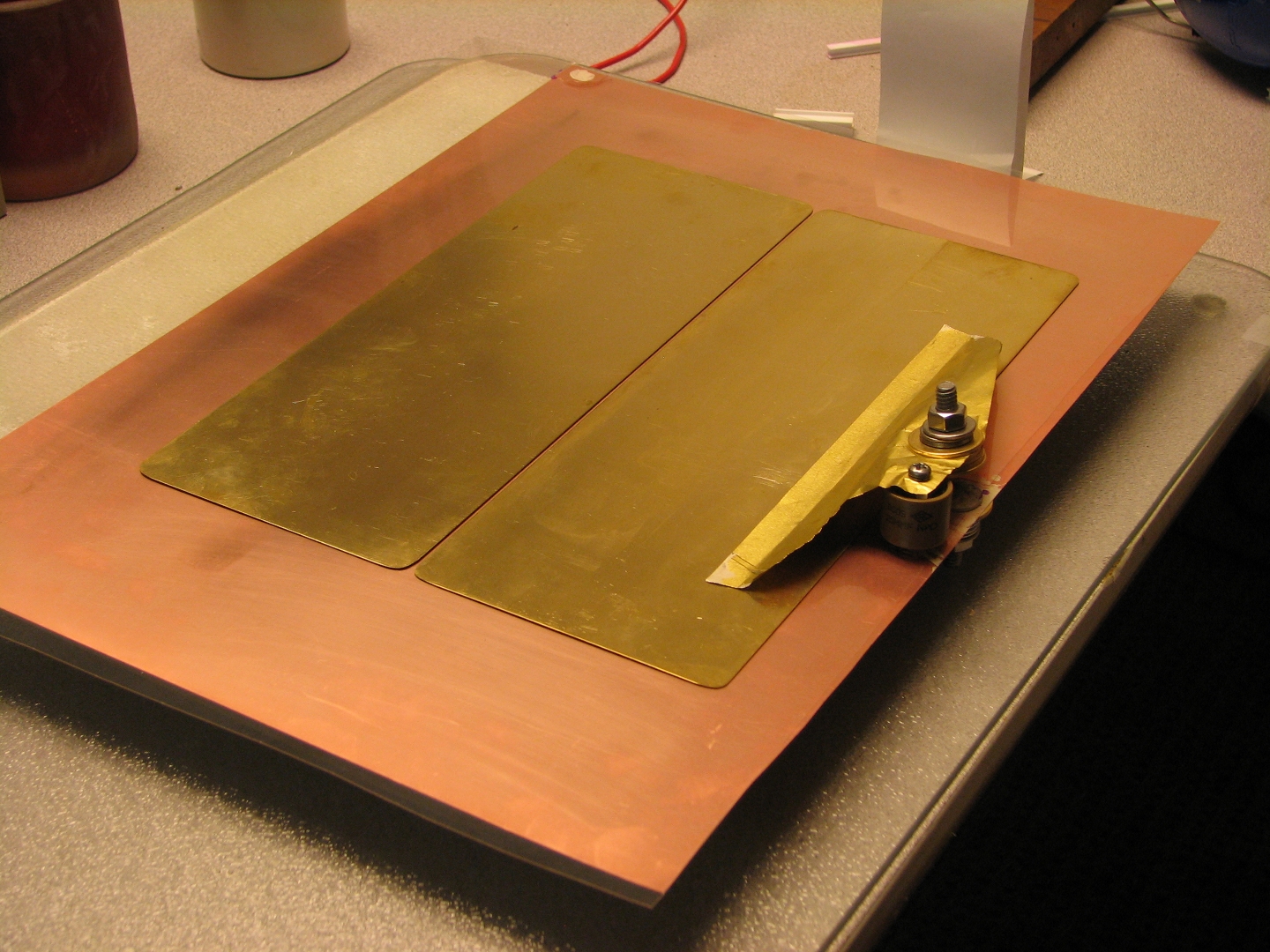
You will need a spark gap to conduct electricity from
one of the capacitors to the ground plane. I made my gap
out of a pair of 1/4-20 carriage bolts, as you can see
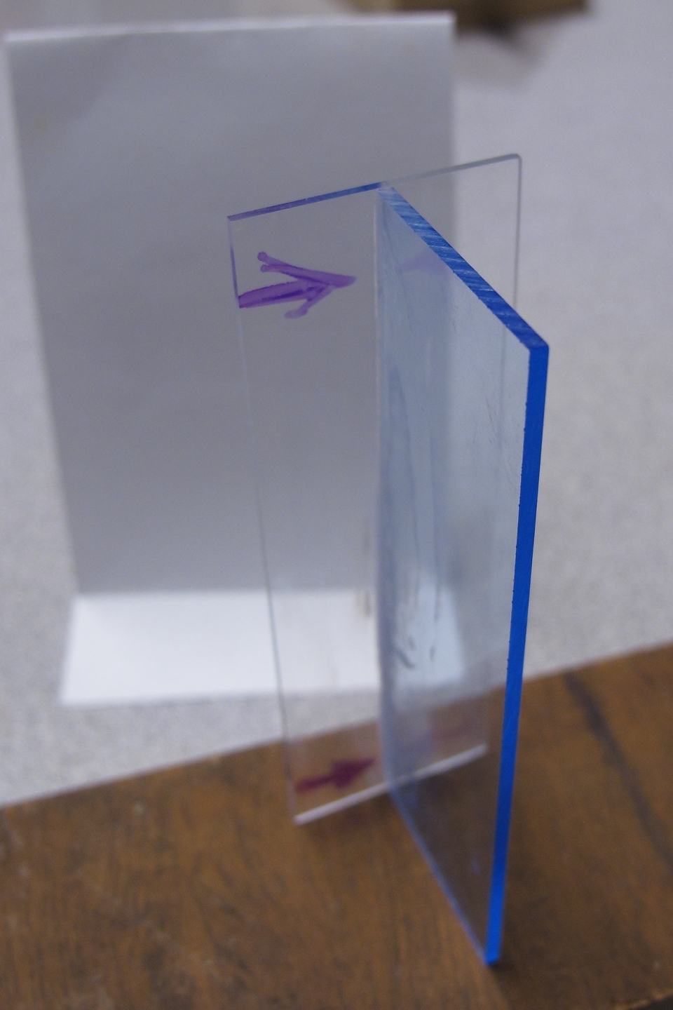
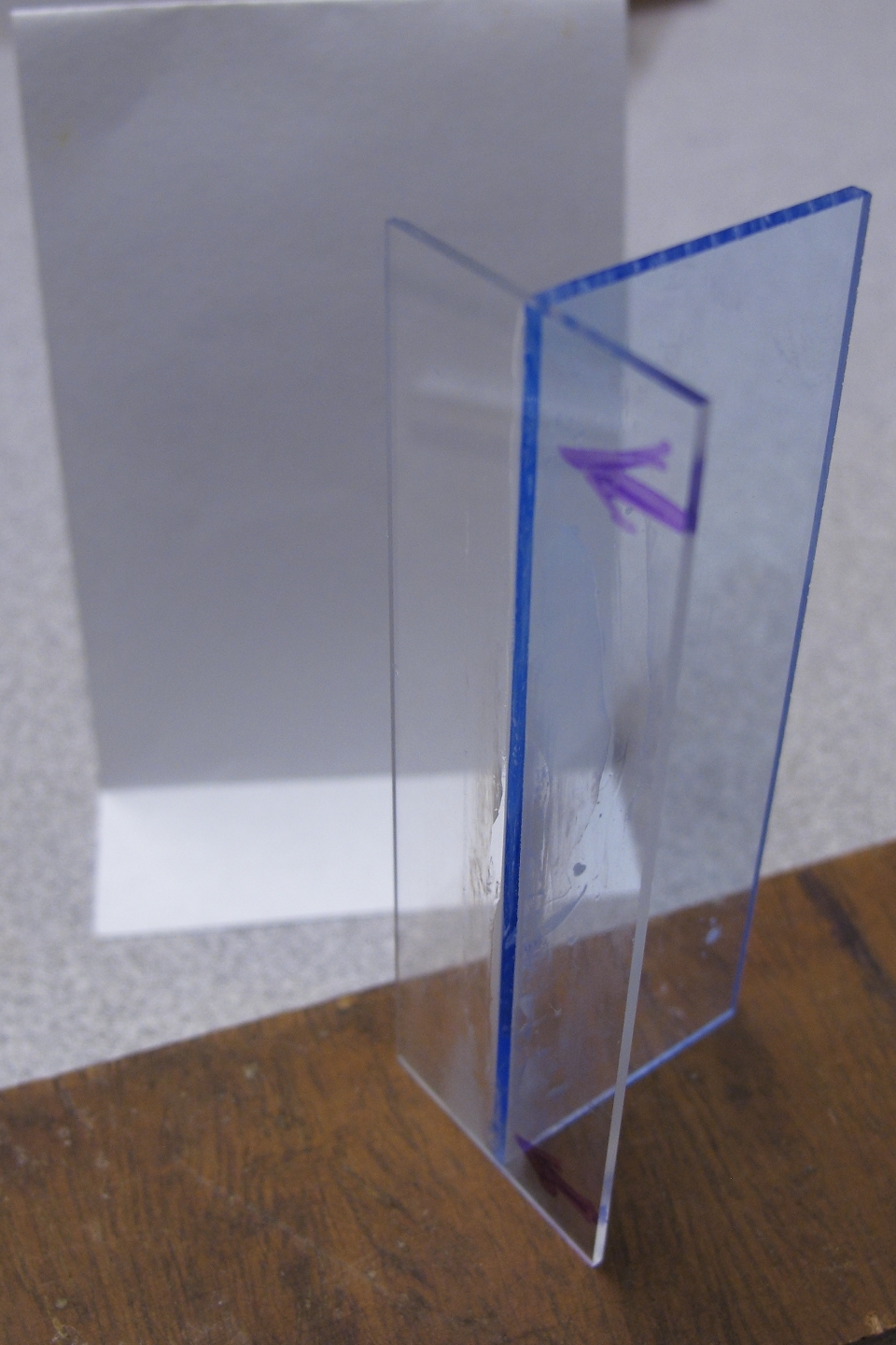
from the photos, below. (Figure 9 shows the initial
version.)
Note: It is not necessary to position the spark
gap where I did. You can put it almost anywhere you
want, provided it doesn’t interfere with some
other aspect of the design. There are some people who
claim that it has to be in or near a corner of the
capacitor, particularly if you want to achieve what is
referred to as travelling-wave excitation; but if you
think about that claim you will notice that in order for
it to be valid, the gap would have to switch in a rather
small fraction of a nanosecond. That’s
considerably faster than is physically possible for a
design of this type. (If you actually have a fast
photodiode and a fast oscilloscope, you can check this
for yourself. You will find, as I did and as you can see
in Figure 26, below, that there is exactly zero chance
of it being accurate. OTOH, it is typically possible to
wedge the electrode spacing so that you get most or all
of your output from one end of the laser.)
(I’m going to presume that you have acquired the parts and materials you need, and that you have a power supply.)
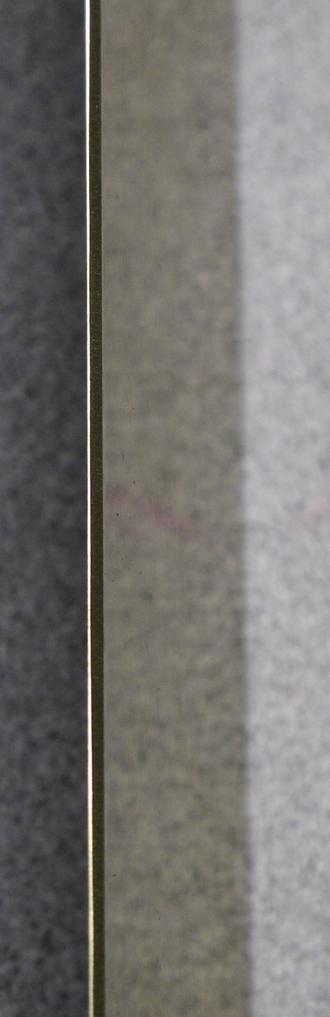
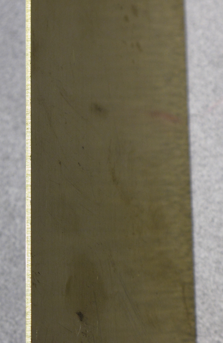
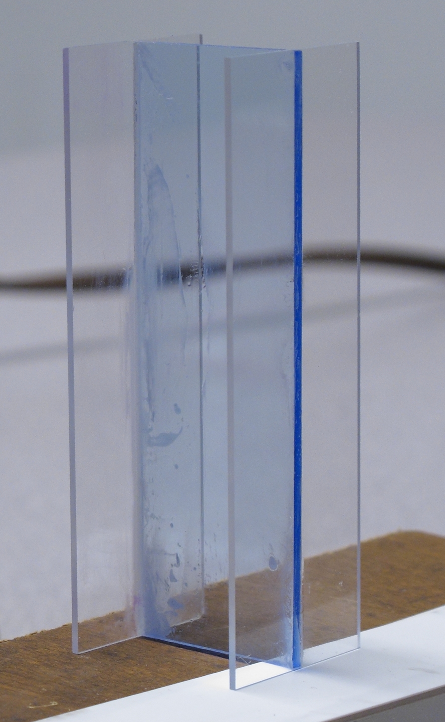
Start by rounding the corners of the brass sheets that
will serve as the top plates of the capacitors. (In this
version, they also serve as the electrodes of the
laser.) Sand the edges at the corners and ends to smooth
them — sharp edges can cause sparking where you
don’t want it, and can sometimes even make it
easier for the high voltage puncture the dielectric,
which immediately causes the laser to fail until you put
a new dielectric into place. You can also make sure that
the edges that face each other and serve as electrodes
are straight and parallel to teach other, and it’s
a very good idea to smooth them and then polish
them. Here are two views of one of the electrodes from
the first version I built:
As you can see, the laser can be made to operate even if you don’t smooth the edges of the electrodes; but it won’t work as well, and it won’t be as easy to adjust. Here is a detail of two new electrodes that I have smoothed and started to polish:
Because the brass pieces are formed by stamping them out
of larger sheets, one face of each is slightly convex
and the other is slightly concave, and the sheets are
almost never really flat. It’s a good idea to put
the convex faces down, as this prevents air from being
trapped under the sheets. Also, if there are sharp edges
it holds them a tiny distance up above the dielectric,
which helps avoid punctures.
The fact that the sheets are not fully flat is another
reason for using weights. In addition to the slight
edge-to-edge curvature imposed by the manufacturing
process, they can also be slightly bowed from rough
handling. If the middle of the sheet is high, you will
want more weight there. (That was what I found with some
of mine, but “your mileage may vary”. If the
ends are high, you can either put more weight there or
very cautiously bend the strips so that the middles are
slightly higher than the ends.)
You need a way to conduct high voltage from one sheet to
the other, so that they both charge correctly. I
originally used resistors, but the first ones I tried
had too much resistance, and the channel sparked every
time the laser fired, so I changed over to an inductor
that I made by winding a few turns of high-voltage wire
around a surplus ferrite core. (You can see this
inductor in several of the photos; it is the blue toroid
with the red wire wrapped around it.) Later I returned
to resistors, but I used a lower value. Either method
can work, but when I tried 200 ohms I found that it is
not enough; a value that low will steal some power from
the discharge. A combination of resistance and
inductance works better than resistance alone, and if
the inductor has enough turns resistors are not even
necessary.
If you use resistors at all, btw, it’s a good idea
to make sure that they are rated for high voltage;
alternatively, as you can see in some of the photos
here, you can use resistors that are encased in ceramic
envelopes and are rated to dissipate several watts: they
seem to withstand the voltages involved. As I say,
though, if your inductor is big enough you won’t
need resistors.
For your inductor, you will need something like 25 or 30
turns around a nonconducting cylinder that is perhaps an
inch and a half in diameter. (I haven’t taken the
time to find the minimum viable number of turns; it may
be less than 25, and it will depend on the diameter of
the cylinder and the turn-to-turn spacing of your coil.)
For convenience and stability you can wind the wire
around anything strong enough to hold it, perhaps a
piece of PVC plastic plumbing pipe if you want to be
relatively fancy about it. I am not fancy; I use the
cardboard cylinder from a roll of toilet paper, which I
stiffen by soaking it with cyanoacrylate adhesive
[“superglue”]. I glue the ends into place
with cyanoacrylate adhesive. This works well, at least
on the type of wire I use.
Here is a photo of a combination that I made; the
inductor is 25 turns, and the resistors are 100 ohms
each. The wire has fairly thick insulation (0.045", a
little over 1 mm); it was the thickest I found at my
local hardware store. It works quite well, and my later
versions do not use resistors.
The upper electrode of the spark gap in my initial
version is mounted on a small piece of brass shim stock
that is attached to the capacitor plate of my laser with
conductive glue, though it is probably sufficient to
hold it down with a weight. In the first version of the
laser I set the lower electrode of the spark gap down so
that it was partly on the ground plane and partly on the
dielectric, in a configuration similar to the one that
Jarrod Kinsey uses (I have a link, above, to a photo of
one of his lasers), and although I used some conductive
glue I also put a weight on it to help hold it in
place. Here is that original gap in operation:
You don’t necessarily need the shim stock: it is
probably fine to connect both sides of the gap the way I
did the lower side, and hold them both down with
weights. That may be trickier to adjust, though —
the spark will jump along the surface of the plastic
unless you put some sort of blockage in place to prevent
it from doing so. (The laser could possibly work with
surface sparks in the gap, but probably not very well;
and the surface sparks would eventually damage the
plastic, after which the high voltage would puncture it
and you would have to replace it. I often use a short
piece of plastic I-beam from the hobby shop as a block
in this sort of circumstance; you can see a piece in
Figure 25, behind the gap. It is necessary to glue the
I-beam (or whatever you use — a cable tie or a
piece cut from one could also work) to the dielectric
with something that is a good insulator at high
voltages, because otherwise the sparks will just sneak
under it. I use “corona dope” (there are
several versions, any of which should work).
Here are some stages in the assembly process:
(Note: this sequence shows wider plates, a
different dielectric, and a more advanced version of the
spark gap than you see in Figure 13. I hope I
don’t have to keep saying that there are lots of
good ways to build these devices.)
(At a later point I replaced the inductor shown here
with the combination of inductor and resistors that you
can see in Figure 8 and in the photo at the top of the
page.)
Note: I connect one side of the power supply to
the baseplane, and the other side to the capacitor plate
that doesn’t have the spark gap on it; but
the laser should work with the connection on either top
plate, as long as both capacitors get charged. You can
test to see whether one way works better with your laser
than the other. You should also test to see which
polarity works better. I usually find that I get better
operation if I connect the positive output of the power
supply to the top plates of the capacitors and the
negative output to the baseplane, but your laser may be
different.
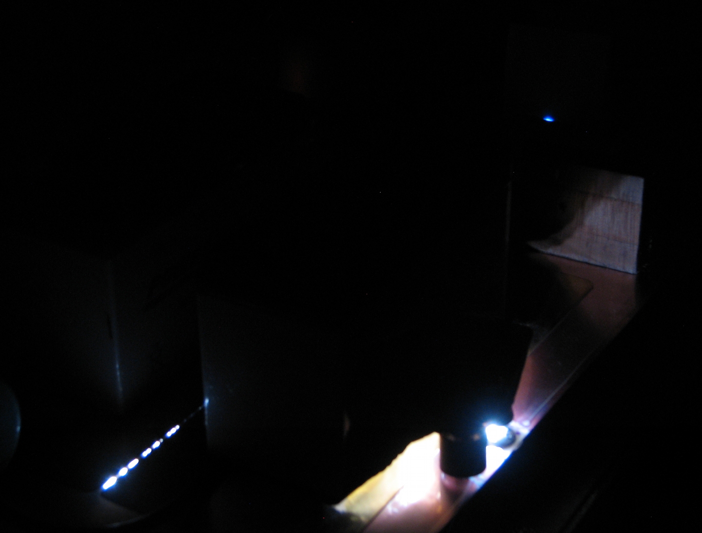
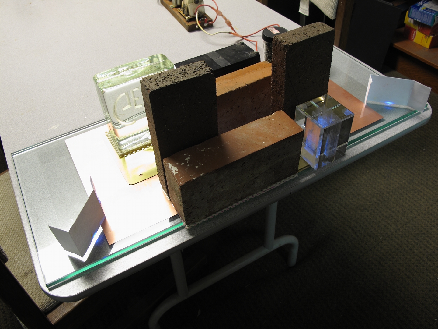
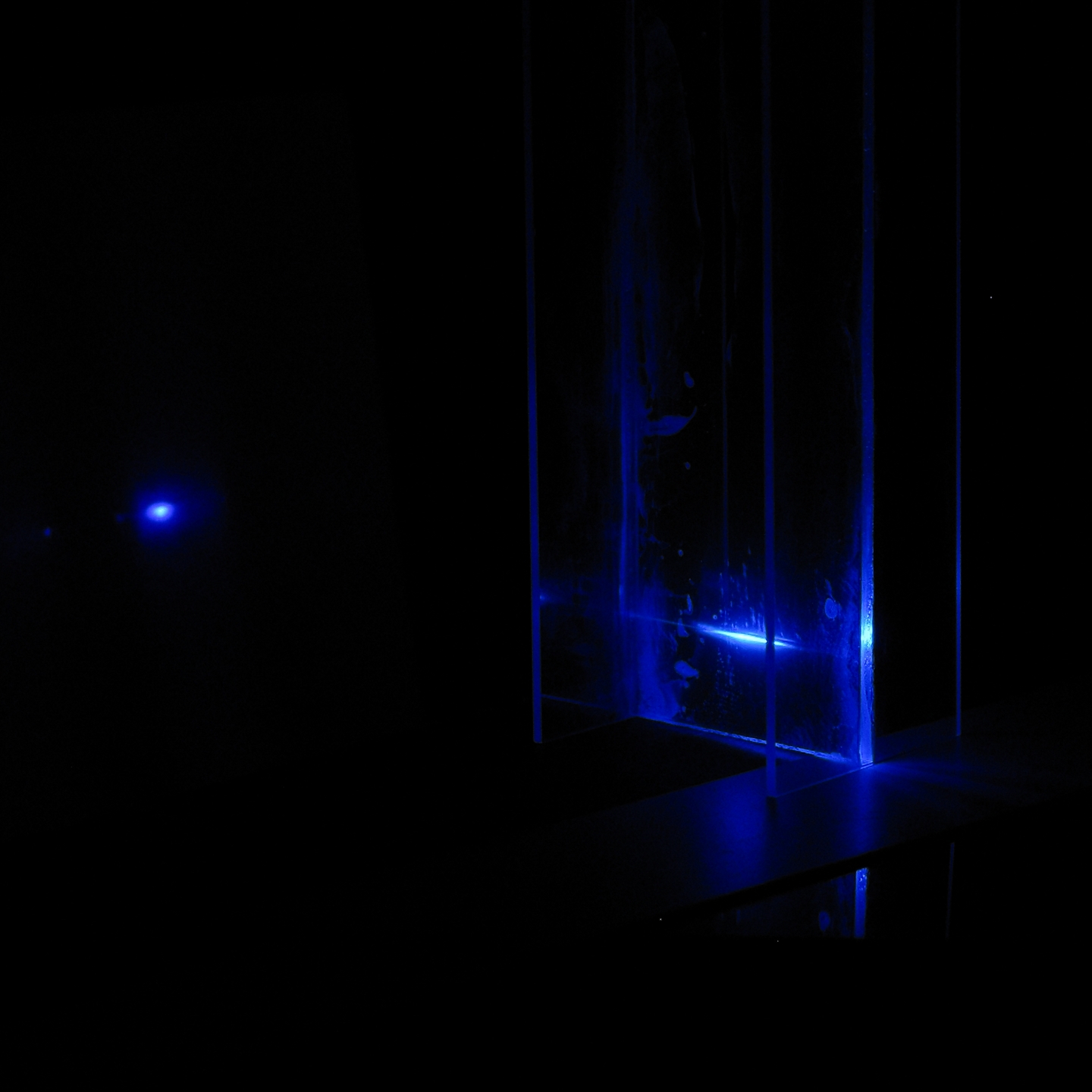
Here is a picture of the output (the small bright spot),
causing a piece of white paper to fluoresce. (The large
diffuse area is light from the spark gap.)
A verbal description of the process of putting one of
these together is likely to be somewhat confusing, so
here is a video to accompany and supplement the photos
above. In this video I build a slightly later and more
advanced version of the laser. (I had just taken it
apart, which is why the voiceover begins the way it
does.)
(Note that the spark gap design you see in this video is different from the ones I show in the photos above. Any of these designs will work.)
Because all of the pieces were already shaped and ready,
because I had just disassembled the laser, and because I
have a fair amount of experience, it took me only 3
minutes and 30 seconds to get it running reasonably
well.
Although this video can give you a fair sense of how to
assemble a simple laser of this type, it is essentially
guaranteed to give you an exaggerated notion of how easy
it is to get one of these machines correctly
adjusted. For one thing, lasers of nearly any sort
almost never work when you first put them together. I
had already built this one several times, though, so I
had a fair sense of some key parameters — for
example, the best distance between the electrodes, which
is about two millimeters or a bit less for this
design. In addition, I have to confess that I have, on
more than one occasion (and as recently as a day before
I wrote this paragraph), spent several hours at a time
trying to adjust a TEA nitrogen laser so it would work
correctly. You need to be patient with the laser, and
you need to be especially patient with yourself.
You also need to remember safety precautions when you
are tweaking, as there is often high voltage on parts of
the laser after you turn off the power supply.
Always turn off the power and short out the HV
before you touch any part of the machine.
First, here is a view of one section of the channel in
normal operation. The tiny white dots on the surface of
the cathode are expectable. They probably indicate that
the channel is being driven strongly, but they are not
necessary for lasing, and I don’t see them as much
when the electrodes have been polished.
Notice that the discharge is not very bright. This is
normal. In fact, it is common to obtain good laser
output from a discharge that appears quite dim to the
eye. (Remember, we are looking for strong UV emission
here, and that does not necessarily correlate with
strong visible emission.)
Note, added later: As I continue to work with
these lasers and to refine my designs, I get to adjust
and observe them quite a bit. In the process I begin to
suspect that I get best output from a discharge that is
just on the edge of sparking, or is showing occasional
bright sparks. My initial guess is that although more
preionization produces a smoother and cleaner discharge,
it also takes more of the energy that is stored in the
capacitors. This decreases the amount that is available
to drive the laser channel.
Here are some conditions that typically do not result in lasing:
If you do not get bright sparks when you first turn on
the power, but you do get them every time the laser
fires, the real question is whether they interfere with
lasing. If there are only a few and they occur only
sporadically, you can probably ignore them; but if there
are lots of them you will want to readjust the laser.
That should get you better output, and it will also help
prevent the electrodes from getting too badly pitted.
If the sparks always seem to occur at the same locations
you probably want to disassemble the laser and clean up
any jaggedness or irregularities on the working surfaces
of the electrodes (and preionizers).
In any case, you can often get some output even with a
fair number of sparks, as you can see in these photos:
If you encounter problems that I don’t list here,
you may want to send me an email message. I can’t
guarantee to be able to help, but at least there’s
a chance.
There are various changes you can make in order to get
better performance from your laser[s]. Some of these
involve fairly extensive rebuilding, some don’t.
First: separate electrodes
As you can see in Videos 1 and 2, I added separate
electrodes to the laser. This helps in several
ways. First, moving the discharge away from contact with
the surface should cause it to take longer to damage the
dielectric. Second, the edges of the dielectric
aren’t always very flat, and sometimes the bumps
or ripples obstruct or interfere with the beam. Raising
the discharge up, even a little, usually eliminates this
problem. Third, having separate electrodes makes it
easier to adjust the channel width, because the
electrodes are not held to the dielectric by
electrostatic attraction, the way the capacitor plates
are. Fourth, having separate electrodes makes it easy to
test various thicknesses and different edge
profiles. (See the addendum about this, below.)
About electrodes: many people who build TEA nitrogen
lasers use cylindrical electrodes, but my experience has
been that round bars want to roll out of position at the
most inconvenient times, so when I built this laser I
chose a different path. I acquired some brass strips at
the hobby shop instead. They turned out to work quite
well. Jarrod Kinsey uses steel rods as electrodes, but
he bends the ends, as you can see in the photo of one of
his lasers that I link to above (where I discuss the
spark gap), partly to prevent them from rolling.
Addendum: Electrode profile
I can’t tell you how your laser will behave,
but I can tell you that when I smoothed and
rounded the edges of the electrodes I was using in mine
I got a significant improvement in performance, and
when I polished them I got another slight improvement.
The discharge is more uniform and a bit less likely
to spark, and the laser is easier to adjust.
Addendum: Angled or wedged electrode spacing
If you’ve built and operated one of these lasers,
you will have observed that there is almost always more
output at one end of the laser than at the other. You
can adjust the electrodes to optimize either end, but
(at least on my lasers) one end is usually easier to
optimize than the other. (Which end this is can change
as you tweak things, though, so you need to be alert.)
It is usually possible to adjust the channel so that it
is slightly wider at one end of the laser, and you can
sometimes get most or all of the output to come from
that end.
I should note, however, that my best current designs
have not been behaving that way. If I attempt to
minimize the output from one end I soon begin to get
less output from the other, and in fact I seem to obtain
best output [at whichever end of the laser is better at
the moment] when the output from the other end is only a
little below its best level.
Second: Preionization
If you have already built and tweaked the initial
version of this laser, you know that it is difficult to
position the edges of the channel to produce a clean and
even discharge. If the electrodes are too close together
or too far apart (or if at least one of them is not
straight), you get arcs and sparks. Finding the
“sweet spot” where the spacing is optimal is
not easy, and can take quite a bit of time and a lot of
fussing.
One thing you can do to make adjustment slightly easier
(and improve the performance at the same time) is to
create a much smaller, separate discharge that starts
before the main discharge and fills the laser channel
with ions and UV light. (Hence the name,
“preionization”.) Preionization is
absolutely crucial for high performance.
If you have separate electrodes, the simplest way to
accomplish this is by sharpening the edge of one of the
capacitor plates. The best shape is not necessarily
obvious, and the positioning of the preionizer is also
important, so you are in for some fussing and fiddling.
After some thought and experimentation, I added separate
preionizers between the capacitor plates and the
electrodes. (Figures 22 and 23 show this configuration.)
Although this makes more things you need to adjust, so
it takes quite a while if you really want to optimize
the laser’s performance, I think it may be worth
the trouble. On the other hand, since I first wrote this
posting I have had very good results using the capacitor
plates as preionizers; they are ideally positioned to
create a surface discharge on the dielectric.
I am using a shape that is actually similar to the edge
profile that
Alfonso Torres Rodríguez
uses for the electrodes of his high-performance
TEA lasers. I create the shape by rough-sanding the
upper edge of one of the capacitor plates at about a
45° angle, but not all the way down — I leave a
little bit of the original edge. It is difficult to
photograph, but
here is Alfon’s image
of his electrode profile (red circle, with diagram below it),
here is a clearer view of one of his earlier profiles,
and here are two views of one of my preionizers, first
showing the narrow bottom edge, and then showing the
angle above it:
[Remember that because I am using this for
preionization, not as a channel electrode, it is
positioned with the narrow edge down, close to the
dielectric.]
It is surprising how rough and informal the profile can
be and still work, though a smoother and more even
profile will give you better performance.
You will have to tweak the various spacings to find what
works best. I must caution you (again) that this process
is usually quite slow, and can sometimes be tedious. I
often find that when I am attempting to tweak at one
end, the performance at the other end changes even more.
In the best-performing versions of the laser, btw, I
have preionizer profiles on both sides of the channel,
and I find that the spacing between them seems to need
to be slightly larger than if I use one plain edge and
one shaped edge. (When the capacitor plates are also
serving as preionizers, the optimal spacing seems to be
at least twice the channel spacing, and possibly even
more.)
Here are two photos taken during assembly. In the first,
the preionizers are in place, in preliminary locations;
they may end up somewhat closer together after I finish
tweaking for best output. In the second I have added the
electrodes, also in preliminary locations. (The next
step is to add weights to hold everything firmly in
place and ensure good electrical conduction. In addition
to the half-brick you see in these two photos, weights
of several sorts are visible in several places,
including the photo at the top of the page and Figure
13.)
Third: the spark gap
The original gap design (see Figures 9 and 13) worked,
but I wanted something that was physically more stable
and that I hoped would switch faster, so I changed to
the design that I show in Video 1. Here is a photo:
(The spacer you can see in this photo did not work well, and is obsolete. I tried various alternatives, but eventually I changed over to the version of the spark gap that is shown in Figure 29, which is stabilized by its components. See the text for details.)
The spark gap spacing determines the voltage at which the laser will fire. If the electrodes of the gap are too far apart, the power supply will be unable to deliver enough voltage to cause the gap to conduct. If they are too close together, the gap will fire very often, and typically the lasing (if you get any) will be weak. If nothing other than the piece of brass shim stock holds the upper electrode in place, it will bounce up and down when you run the laser. This can cause peculiar variations in the firing rate, but at least in some cases it can actually stabilize operation.
Important: remember to use an insulated tool when you adjust the spacing of the gap, unless the power supply is off and you have shorted out the HV.
Addendum: a “start” capacitor
There is another thing you can do to the spark gap that will improve the operation of the laser. It turns out that an additional capacitor, connected directly across the gap and positioned close to it, causes it to form a better conduction channel and to form the channel more quickly. This has two results: the laser works better in general, and the pulse-to-pulse uniformity is much improved. You can see this capacitor in Figure 25, below; it is the small brown cylinder, just to the left of the gap. (It should be as close to the spark gap as is practicable.)
Because the capacitors that comprise the laser are not
very large themselves (perhaps 1500 to 5000 picofarads
each, depending on construction details), the
“starting capacitor” has to be quite small;
I am currently using a 25-picofarad
“doorknob” capacitor that I had in my
junkbox, but there should certainly be other ways to
accomplish this. The precise value is not very
important, as long as the value is small compared with
the capacitances of the laser. You do need to be sure,
btw, that it will handle whatever voltage your power
supply can deliver. Here is a photo, showing the gap
with a start cap in place:
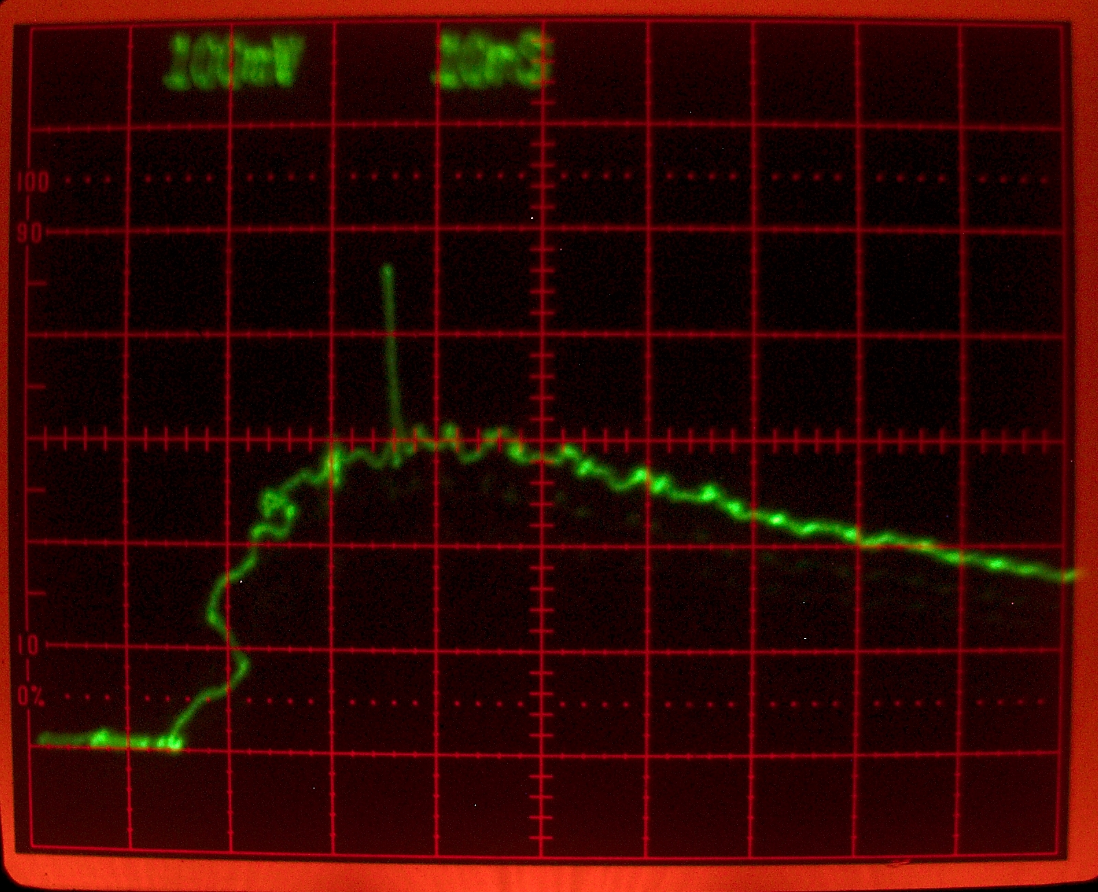
Here, in case anyone is interested, is an oscilloscope trace:
(My apologies for the electrical noise that is
superimposed on the trace; it is difficult to shield the
detector and the oscilloscope from the nasty EMP that
the laser generates when it fires. The noise, btw,
looks
very much the same
from trace to trace.
I guess that the way it is generated and the way the
scope responds to it don’t change much.)
In this trace it takes about 24 or 25 nanoseconds for
the electrical pulse to reach peak power. (In some
others it seems to be as fast as about 16 or 18 nsec.)
The laser pulse occurred at about 18 nsec, but the light
from the laser had to travel about two feet farther than
the light from the spark gap (it went out to the side,
to a mirror that reflected it into the detector), so it
reached the detector about 2 nsec later than it would
have if the pathlengths had been the same. I have put a
mark on the trace where it should be. (I find it
interesting that even with a simple DIY laser we are in
a regime where this is an issue. Making comparative
measurements involving really short laser pulses
must be a nightmare.)
It would be best for the laser to reach threshold when
the electrical power is just reaching its peak, but at
least it’s fairly close. I also suspect that
it’s better to be on the upslope than on the
downslope. Either way, the laser pulse is only about 1
nanosecond long, the electrical pulse is far longer, and
it is therefore clear that most of the energy stored in
the capacitors is wasted. This is not (and cannot be) an
efficient laser.
If you are really interested, you can redesign the spark gap so that it is externally triggered. That will give you far more control over when and how often the laser pulses. It is also likely to improve the performance, partly because it allows the power supply to charge the laser up until you trigger the gap, rather than when the gap fires on its own, and the capacitors store more energy at the higher voltage.
I must, however, note that a triggered spark gap without a trigger pulse is an untriggered spark gap. I am, at least initially, using a commercial trigger unit that we bought on eBay, because I don’t have time to design and build one myself right now. (If I do end up building one for this project, though, I will post the design here. I will note that a triggered gap of this type tends to require a that doesn’t have to have much energy in it, but it does need to be fairly fast — the risetime should be less than 1 microsecond. The pulse from an automotive spark coil is much too slow, though there may be ways to finesse that.)
To construct the new upper electrode for the gap, I took
a short brass 1/4-20 bolt and drilled a hole down the
middle of it, or as nearly down the middle as I could. I
then drilled out the hole with a slightly larger bit, so
that I could easily fit a piece of glass capillary
tubing down it. I am using melting-point capillaries
that we acquired on eBay for a different project. The
brand is not crucial, and in fact there are even several
types of capillary tube that will work, not just the
ones for determining melting points. The ones I’m
using came in a container that looks like this:
One end of each tube is closed, but I already had some
that I had shortened by cutting off the closed end. (You
need to be quite careful when you do that, as these are
thin-walled and very delicate. It’s a good idea to
wear gloves. I moistened the outside of the tube, scored
the wall lightly, and just pulled. I cut several of them
this way, and most of them broke cleanly.) I also
drilled a smaller hole, one that the capillary tubing
would just fit into, through an acorn nut, as close to
the peak as I could get it. Here is the preassembled
head, but without the trigger electrode:
NOTE: unless the holes line up very nicely, it is important to attach the tubing to the bolt with a flexible glue. (Yes, I found this out the hard way, by using CA glue at first, and had to remove the remains of the tubing from the bolt after I tried to put the acorn nut on. As you can see in Figures 29 and 30, aquarium caulk is your friend here.) In case it isn’t obvious, you do not want to glue the tubing to both the bolt and the acorn nut, as that would make it difficult or impossible to adjust. You could glue it to the acorn nut instead of the bolt, but the bolt has more contact area and is not going to be exposed to hot plasma. For this reason I didn’t try plastic tubing, though that might also work. Jarrod Kinsey has suggested the thin tubes that often come with (for example) aerosol cans of lubricating oil as a possibility here.
I am using a piece of broken jeweler’s saw blade as a trigger electrode. It was handy, and it is fairly hard steel, so I hope it will last a little while. (This is really only the second time I have built a triggered gap, and the first one was much different, so I do not yet know whether the saw blade was a good idea. I’ve put over a hundred shots on the laser with the new gap in place, though, and it seems to be fine.)
Here is a photo:
As seems to be usual with this style of gap (if I recall correctly, it is called a “trigatron”), I have the positive output of the trigger-pulse generator connected to the trigger electrode and the negative output connected to the acorn nut. I also have the positive terminal of the power supply connected to the upper plates of the capacitors. Initially, I was using only one “starting capacitor”, as you can see in some of the previous photos, but later I added a second one.
(Parenthetical note: I tried to get an oscilloscope trace of the light from this gap, but the electrical noise was so bad that I was unable to do so.)
I eventually changed the gap design again. I am now using a carriage bolt as the top side, just as I do for the free-running versions of the gap; I drill the hole starting at the head end of the bolt, so that it is centered where that’s important.
Fourth: the dielectric and the capacitor plates
I was able to get some acetate sheet (which you can see
in Figures 10-12 and 22-23) from a vendor on
eBay. Acetate has higher dielectric constant than most
of the other plastics I’ve been using, which means
that at any given voltage, a capacitor made with acetate
will store more energy than a capacitor made with, for
example, styrene, provided the sheets are of the same
thickness. The capacitance is higher if the dielectric
is thinner, and the acetate sheet that I acquired is
only about 6.5 mils thick, which gives it another
advantage over the 10-mil styrene sheet I was using
earlier.
Because this sheet is so thin, however, it can’t
handle as much voltage as a thicker sheet, and I have to
adjust the spark gap so it fires about 2 or 3 times a
second. At one point I allowed the time between pulses
to get too long, which let the voltage on the capacitors
rise too high; a puncture promptly developed in the
sheet I was using, and the laser stopped working until I
swapped it out and tightened the spark gap
spacing. (Even 2 pulses per second doesn’t really
seem to be enough; the voltage has punctured two more
pieces of acetate sheet since I first wrote this
paragraph, one of them twice. Fortunately the first hole
was very close to a corner, and I was able to move the
capacitor plates slightly to avoid it. [I put a droplet
of corona dope over the hole to prevent sparks from
going through it.]
In addition to finding a thinner dielectric with higher
dielectric constant, for this version of the laser I
changed to capacitor plates that are 4" x 10", so they
have more area. (You can see these plates most easily in
Figure 11, but they are also visible in Figures 12, 22,
and 23.) This also increases the capacitance, and thus
the amount of energy the capacitor stores at any given
voltage. (With these plates, though, I have to use
separate preionizers because the electrodes are 12"
long.) The capacitance, btw, calculates at just over 5.5
nf; but when I measured it I found that the actual value
was only about 4.2 nf. I am not entirely sure what is
responsible for the difference, though it is entirely
possible there is still a small amount of air trapped
between the plates and the dielectric.
When I built the triggered gap I returned to 10-mil styrene and 2" x 12" plates, because I wanted to be able to pause between pulses. With the thin acetate sheet, that would not have been possible.
All of the lasers on this page use a circuit topology
that is probably best described as a simple
voltage-doubling circuit, though it does not actually
double the voltage. (There doesn’t seem to be a
better term for it.) There is also a different topology
that you can also build, a Charge-Transfer Circuit.
In the doubler circuit, you charge up both capacitors
and then short-circuit one of them to ground (or, in the
machines I describe here, to the opposite power supply
polarity). For reasons that are described elsewhere,
this causes a large voltage to develop across the laser
channel, which is between the two capacitors, very
rapidly. The flow of current from one cap to the other,
across the channel, drives the laser.
In the CT circuit, on the other hand, you charge up one
capacitor, which serves at the main energy storage point
for the laser. You then discharge it into a second,
smaller capacitor through a high-voltage switch
(typically a spark gap) that is between them. The
smaller capacitor starts the laser channel conducting,
and then both capacitors drive the laser.
Each of these circuit topologies has advantages and
disadvantages. The doubler circuit is efficient,
symmetrical (it has been found, both theoretically and
experimentally, that it provides best performance when
the two capacitors have the same value), and easy to
construct. The CT circuit is not symmetrical, is usually
less efficient, and is often somewhat less easy to
build; but at its best it can perform quite well.
(See the nitrogen lasers built by Alfonso Torres
Rodríguez; there’s a link to his site,
above.)
The main store of a CT circuit (often referred to as the
“dumper” capacitor) can have relatively
large value, and it does not have to be as fast as the
capacitors in the doubler circuit, both of which must
drive the channel directly.
One other advantage of the CT design is that you can
eliminate the charging inductor or resistor-inductor
combination. You are only charging one capacitor, so you
don’t need or even want a connection to the other
one. (In principle, you could put the connection between
the peaker capacitor and the ground plane,
to discharge the peaker between pulses; but I
have not seen very much difference with a discharging
inductor in position, so I usually don’t bother
with one.)
Here are photos that show the assembly of a
straightforward CT design that is closely related to the
doubler designs I’ve presented above. The dumper
capacitor is a 6" x 16" piece that I cut from a brass
kickplate. The peaker capacitor is a brass strip, 2" x
12". This laser uses separate electrodes, which raises
the channel up from the surface of the dielectric and
allows the top plate of the peaker to be used as a
preionizer. The spacing between the top plate of the
peaker and the other brass strip is not optimized in
these photos. Note: on the side of the channel that is
connected to the baseplane, there is no dielectric. The
brass strip on this side, which supports the electrode,
should be enough thicker than the top plate of the
peaker cap to compensate. (With 10-mil styrene as the
dielectric, I used a 16-mil strip as the peaker and a
25-mil strip on the low side. When I changed over to
5-mil Dura-Lar™ [a polyester film that is similar
to Mylar] I used a 25-mil strip as the peaker, and a
32-mil strip on the low side. I use the same combination
when I have two of the 5-mil sheets under the dumper,
because I am still using only a single sheet under the
peaker.)
I used a thick glass plate as a base, partly because
there is enough weight on the laser when it is assembled
that if I didn’t provide a stiffener it could flex
the top of the table, depending on where I position
it. That would put a curve in the channel and prevent
the laser from working properly.
Here is a view of the channel, with two sheets of 5-mil
Dura-Lar as the dielectric for the dumper and a single
sheet as the dielectric for the peaker. The dumper for
this version of the laser was a piece of brass shim
stock, 6" wide and about 28" long. (The baseplane for
this version of the laser, which I built in February of
2012, is a piece of 12"-wide brass shim stock, also
about 28" long.) I measured the dumper capacitance as
just about 10 nf and the peaker capacitance as 2.9 nf,
but I don’t know how accurate my meter is. The
channel was adjusted extremely well, and the unfocused
beam easily drove a cuvette of “Optic
Whitener” that was at least 8" away from the end
of the channel, with the laser pulsing a bit faster than
1 Hz. There are occasional bright sparks, but very few,
and they do not appear every time the laser fires. The
tiny white sparks (which Jarrod Kinsey refers to as
“icicle sparks”) do, on the other hand,
appear every time. They are on the cathode (negative)
side. There is a dim violet glow in the channel when the
laser fires, but it can be hard to see, and the camera
doesn’t seem to pick it up very well. (Remember,
we are looking to get UV out of the laser, not visible
light, so a discharge that appears dim to the eye is not
necessarily underpowered.)
With 5-mil polyester film as the dielectric for both
capacitors the channel needs to be wider for best
operation, and it has more and longer “icicle
sparks”. It may also require more preionization.
Unfortunately, unless the laser is pulsing several times
a second, a single 5-mil film used as the dielectric for
the dumper typically lasts only a few hundred to a few
thousand pulses, so I am using two sheets.
Here is another Charge-Transfer design.
It uses a small Marx bank as its dumper capacitor and
provides even better performance, but at the expense of
added complexity.
Here are some reference points you can use if you want to.
At some point, you probably start coming up with your
own ideas for improvements, or for entire designs. This
isn’t something that can be placed in the
sequence, so I am not giving it a number.
I encourage you to try various ways to improve the
performance of your laser or lasers, and I strongly
suggest that you keep a comprehensive notebook that
includes photos, and you should take photos not only of
things that worked but also of mistakes, and of things
that didn’t do what you wanted them to or thought
they would. It can save you from much headpounding, and
from having to learn things repeatedly.
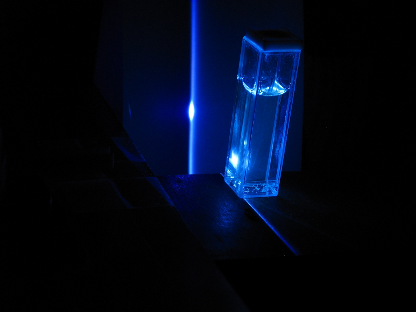
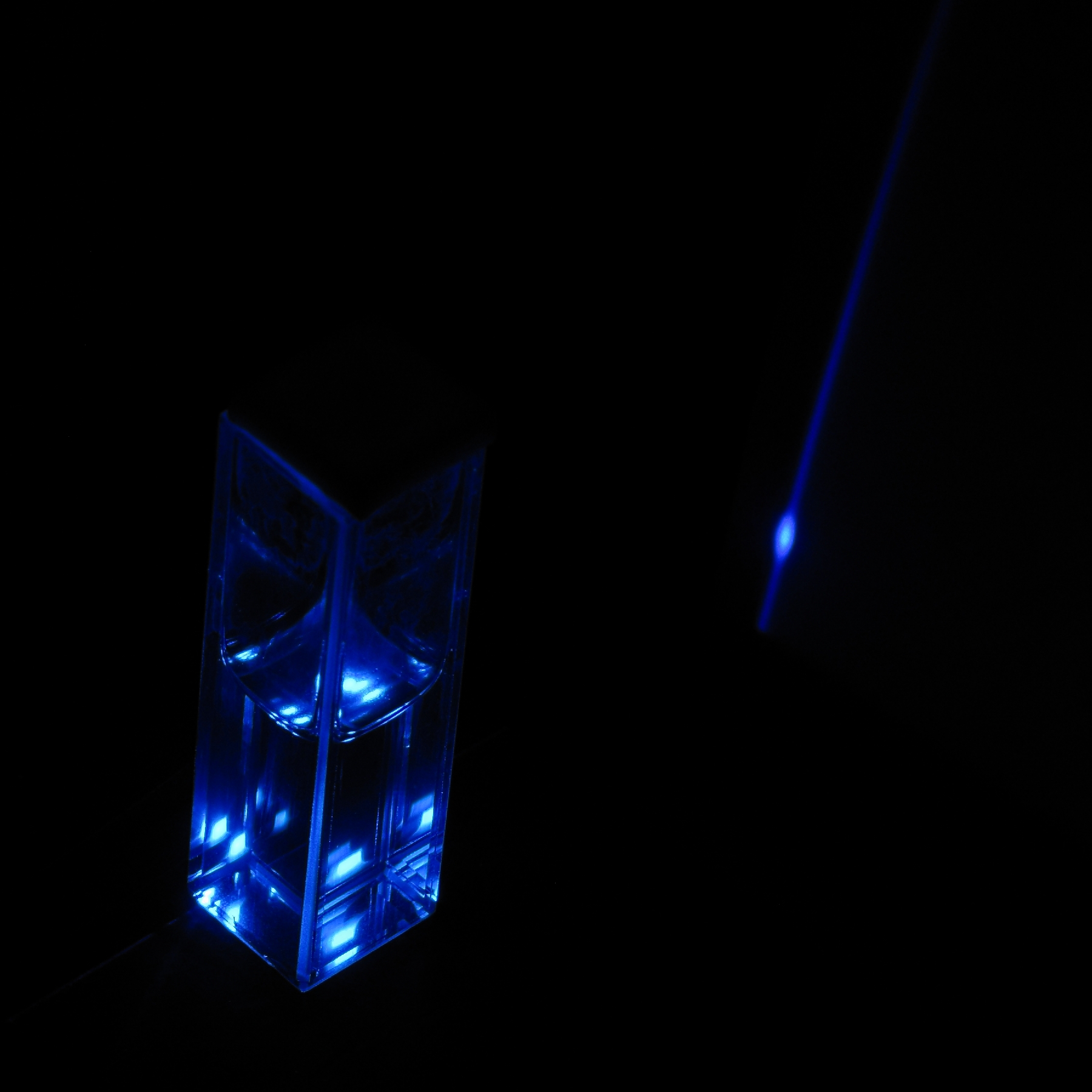
One of the most common uses for the nitrogen laser is as
a pump source for organic dye lasers. As I mentioned
above, in the listing of milestones, this can serve as a
rough indication of the output power.
The total energy stored in the original version of the
laser (10 mil styrene and 2" x 12" plates) was probably
close to 200 millijoules. That version could drive a
small dye laser if I used a cylindrical lens to focus
the beam onto the front of the dye cuvette. Some of the
later versions can drive a small dye laser even if I
don’t focus the beam. (I’ve mentioned this
as one of the progress steps, above.) The photo on the
left, taken from in front of the cuvette, shows this
with nitrogen in the channel. After I got that version
adjusted a bit better I was able to get enough output
even with air in the channel. (Photo on the right, taken
from behind the cuvette.)
(The brighter spot is the dye solution using the walls
of the cuvette as mirrors. The tall diffuse stripe is
lasing without feedback, often referred to as ASE
[“Amplified Spontaneous Emission”].)
Although I used a commercial dye and a fused silica
cuvette in these photos,
Video 4
shows a dye cell I built out of microscope slides, glued
together with silicone aquarium caulk. In this video I
use the focused output of the nitrogen laser to drive
three different commercial fountain pen inks. (I have
actually lased five fountain pen inks so far.)
I’ve already mentioned “Optic
Whitener”, which is another excellent laser dye
for the DIYer, and you can even get fluorescent dyes
from some highlighter markers, though they are not
always optimal for nitrogen laser pumping. (If you use
isopropyl alcohol to extract the dye from a Sharpie
“Accent” yellow-green marker like the one
that you can see in the photo at the top of the page,
you get a solution that seems to work fairly well. It is
quite concentrated, and you will need to dilute it, just
as I diluted the inks I used in the video.)
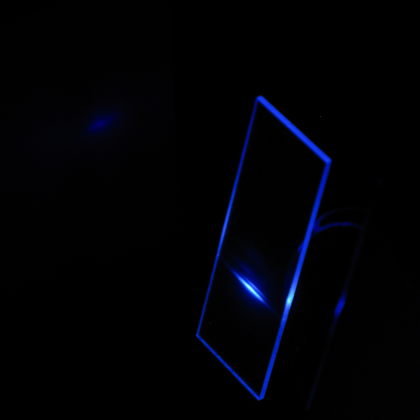
If I focus the output, the nitrogen laser can also drive
a piece of commercial fluorescent plastic:
The edges of the sheet are not smooth or glossy, so its
output is very diffuse. I decided to clean up one edge,
but polishing it would have been difficult, so instead I
glued a microscope slide to it, using cyanoacrylate
adhesive (“CA”; “superglue”).
(In retrospect, I should have used either a different
type of CA, or epoxy. The thin glue is difficult to
control, and it got on some places where I didn’t
want it.)
This resulted in a slightly improved output pattern:
(Taken with air in the channel of the nitrogen laser.)
One slide provided enough improvement that I decided to
add a second one. When I line up the beam of the
nitrogen laser so that it is perpendicular to the slides
and the dye can use them as mirrors, this works quite
well:
My designs started as variants of designs developed by
Jarrod Kinsey; I have introduced a number of changes,
partly for ease of construction, partly because of the
materials I can get, partly because of the way I think
about the issues involved here, and partly to point up
the fact that this is not a “one right way”
situation. Just because I do something a certain way
does not mean you have to do it the same way if
you can’t find the part or material that I use, or
even if you just want to do it differently. If you
decide to do something differently, though, or if
circumstances oblige you to, you will want to think it
through before you build it, so you’ll have some
idea of how your version is likely to work, ...unless
you are willing to spend some time and effort on what
could end up being a lengthy trial-and-error method. [I
am hoping to provide some background information on a
separate page, to help you understand how these lasers
work and what the important parameters are. I also
provide links to pages that other people have written
about their nitrogen lasers, for comparison.]
Jarrod’s designs, in turn, are based partly on
designs and suggestions from other DIYers including
myself (there are no one-way streets here!) and Milan
Karakas; partly on his own experiments; and, though not
as directly, partly on articles that have been published
in the scientific literature.
Just as I made a number of cogent suggestions to Jarrod
as he developed his designs, he has made a number of
cogent suggestions to me as I developed the designs on
this page, and I am indebted to him for his help on this
project. I am likewise indebted to Milan Karakas, who
asked several key questions and provided crucially
important advice relating to the performance of the
lasers, particularly with regard to preionization and
switching.
The preionization method that I use in the improved
versions of the laser was inspired by a feature that
Alfonso Torres Rodríguez uses in his TEA
lasers. My spark gap design was partly inspired by two
high-speed spark gap designs that I encountered in the
scientific literature, and partly by what I could get at
the hardware store. The power supply is my own idea.
I must also acknowledge my indebtedness to Ernest
E. Bergmann, who developed some of the earliest
room-pressure nitrogen lasers, and whose papers have
been extremely helpful to me; to Professor Mark Csele,
who has done superb work with a number of DIY-feasible
lasers and has published fine Web pages about them; and
to Sam Goldwasser, for his amazing Laser FAQ. (Links,
below.) If I have left anyone out, I hope they will
forgive me...
===============================================
Alfon also has
a number of YouTube videos
showing some of his lasers in operation.
[Although it is somewhat peripheral, you may want to read
my rant about the explanation that is in the Scientific
American “Amateur Scientist” nitrogen laser project.
— There are some potentially useful references at the end.]
===============================================
Sam’s Laser FAQ
is an incredible resource, covering a tremendous variety
of laser types. My one caveat is that in addition to a
lot of important information there are many opinions,
some of which are more credible than others. When you
see descriptions of a laser or a project, or
specifications of a commercial device, they are
generally quite reliable; when you see someone stating
that dye lasers are not worth the trouble (because he
barely managed to threshold Rhodamine 6G with 200 joules
into his flashlamp), that’s not necessarily as
reliable. (It is entirely possible to threshold some
dyes
with just a few joules into a flashlamp,
but it is extremely difficult to threshold R6G or any
other dye if you drive your flashlamp with capacitors
that are not well adapted to fast-pulse service. This
clearly includes photoflash capacitors, though they are
admirably suited to slow pulse service.)
===============================================
Here is a page
on which I hope to provide additional technical
information about TEA nitrogen lasers, the principles on
which they work, circuit topologies, and so on. As of
late 2011 I am just starting to work on it, so please
bear with me if you find it mostly empty. (You can
always email me with questions.)
To the top of the LASERs section
Email: a@b.com, where you can replace a with my first
name (jon, only 3 letters, no “h”) and b
with joss.
Phone: +1 240 604 4495.
Last modified: Thu Sep 13 00:59:08 EDT 2018
Parts and Materials
Construction:
1. The Power Supply
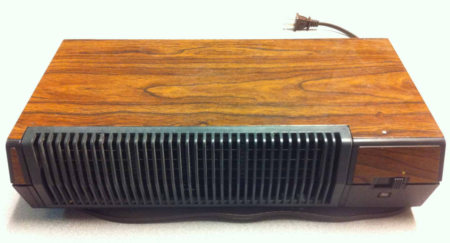
Figure 2: The air cleaner
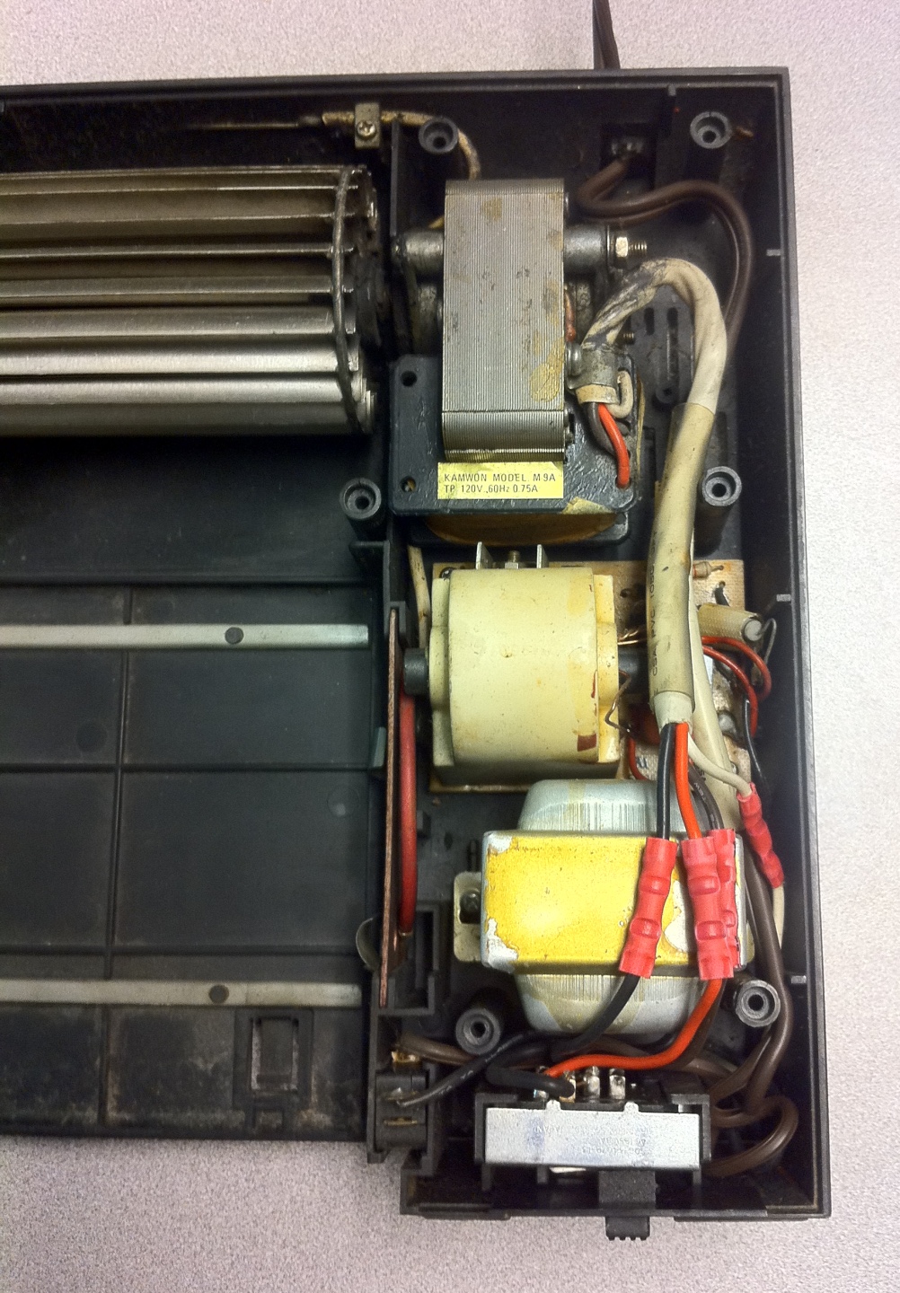
Figure 3: Interior of the air cleaner
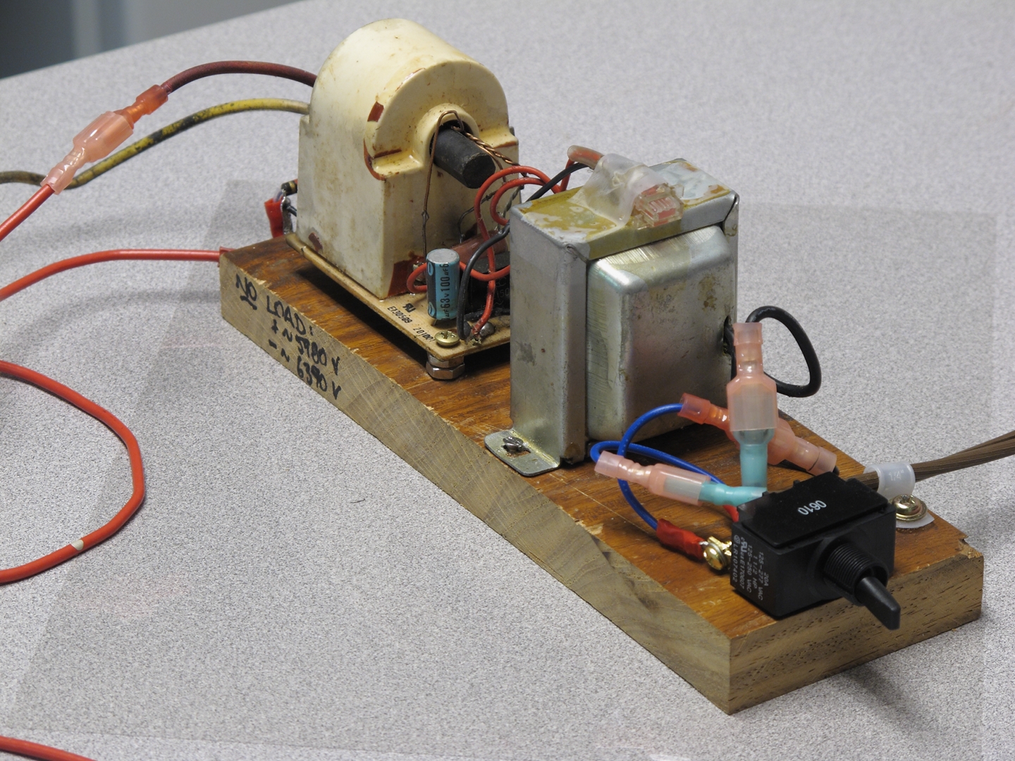
Figure 4: The power supply
Construction:
2. Parts
Construction:
3. The Laser Itself
![]()
Figures 5 & 6: Electrode edges
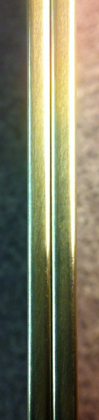
Figure 7: Polished electrode edges
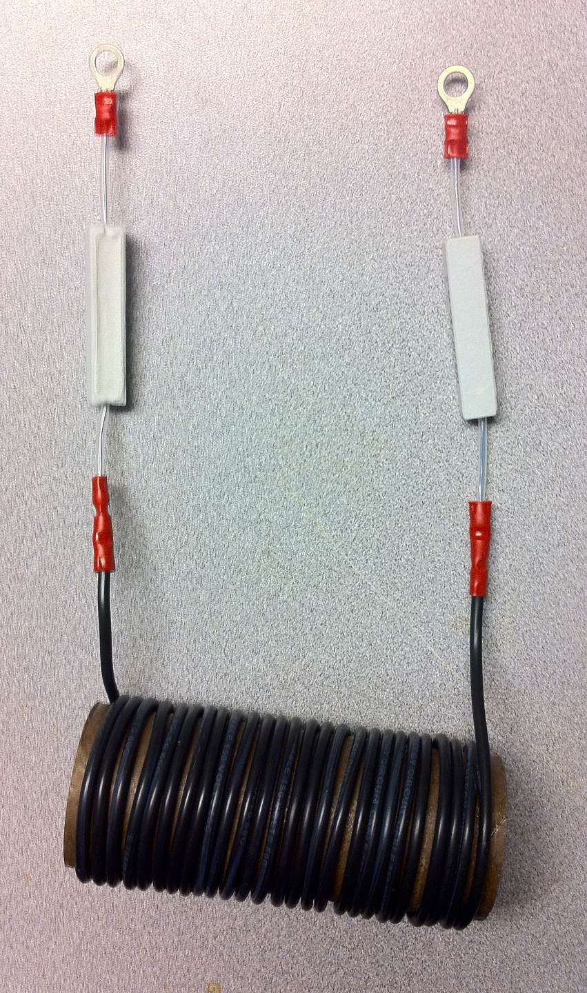
Figure 8: Resistor-inductor combination
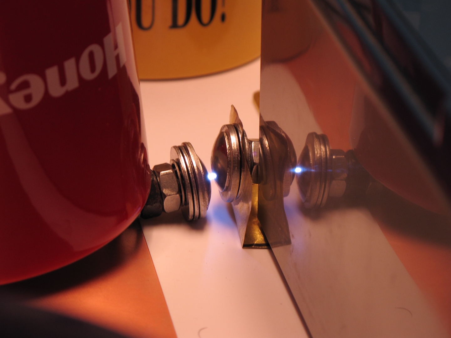
Figure 9: Spark gap, initial version, in operation
Construction:
3A. Assembly
Figures 10-12: Assembly
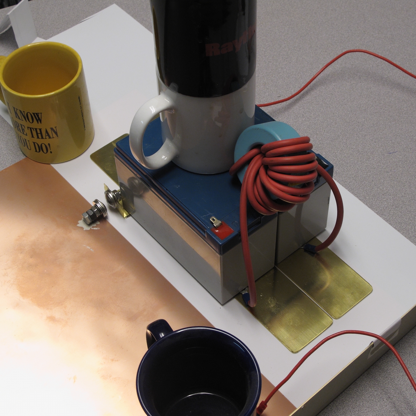
Figure 13: Overview of an early version
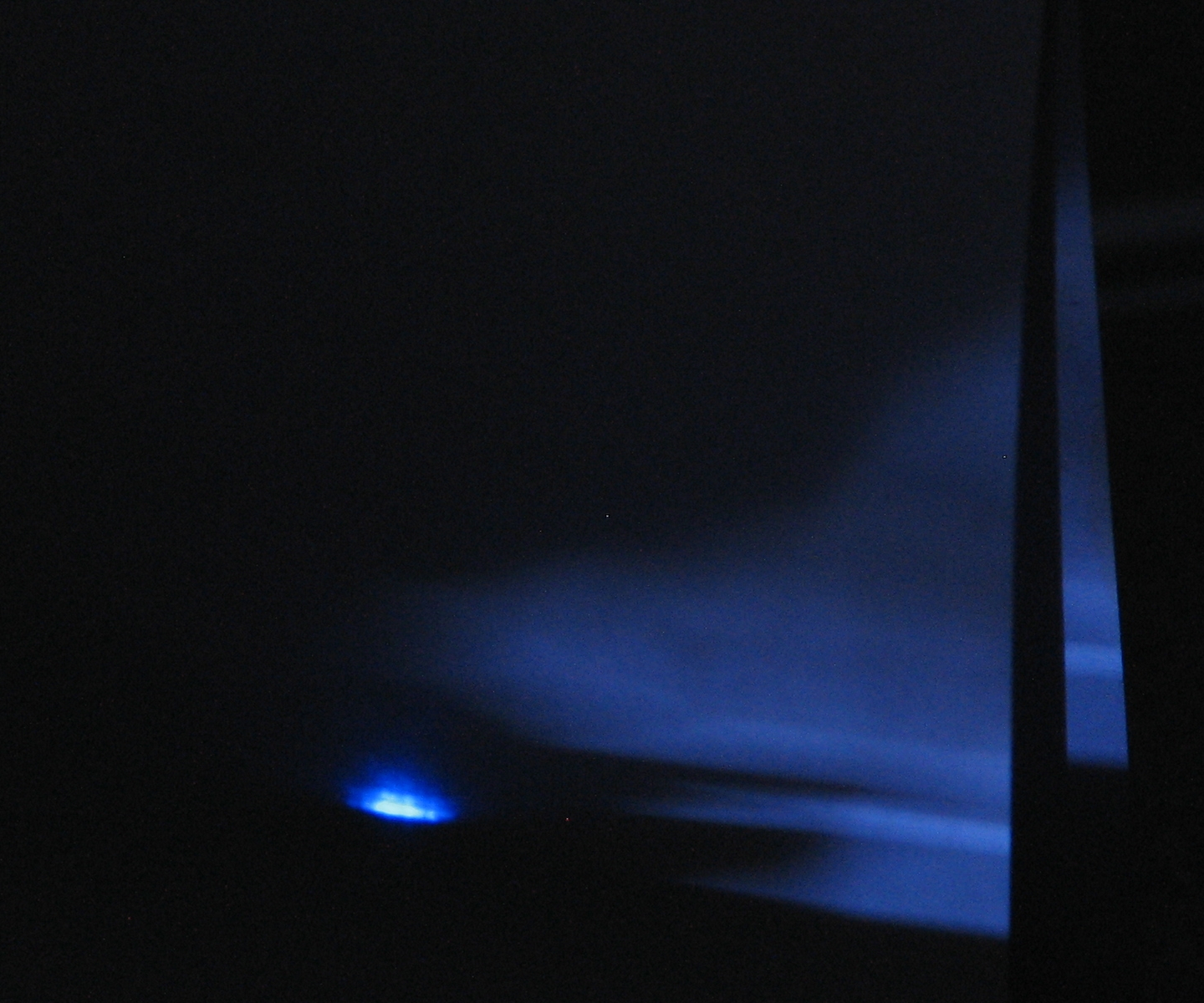
Figure 14: Output from the simple version of the laser
--> CAUTION <--
Signs and Symptoms:
Working and Nonworking TEA Nitrogen Lasers
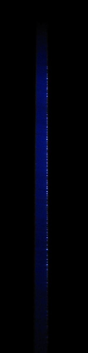
Figure 15: Normal discharge in the channel
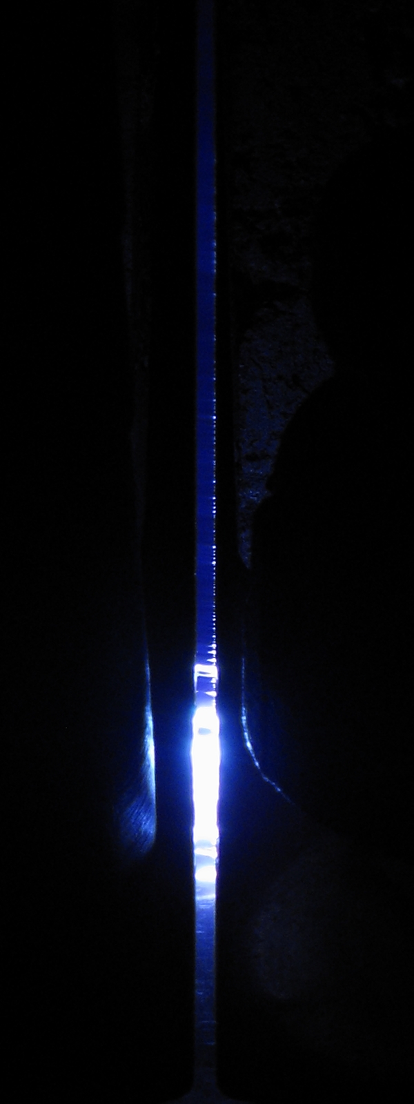
Figure 16: Electrodes too close together
![]()
Figure 17: Electrodes much too far apart
Figures 18 & 19: Lasing with sparks in the channel
Continuing Progress:
Improved Performance and Advanced Versions
Figures 20 & 21: Edge profile of my preionizer
Figures 22 & 23: Preliminary positioning of preionizers and electrodes
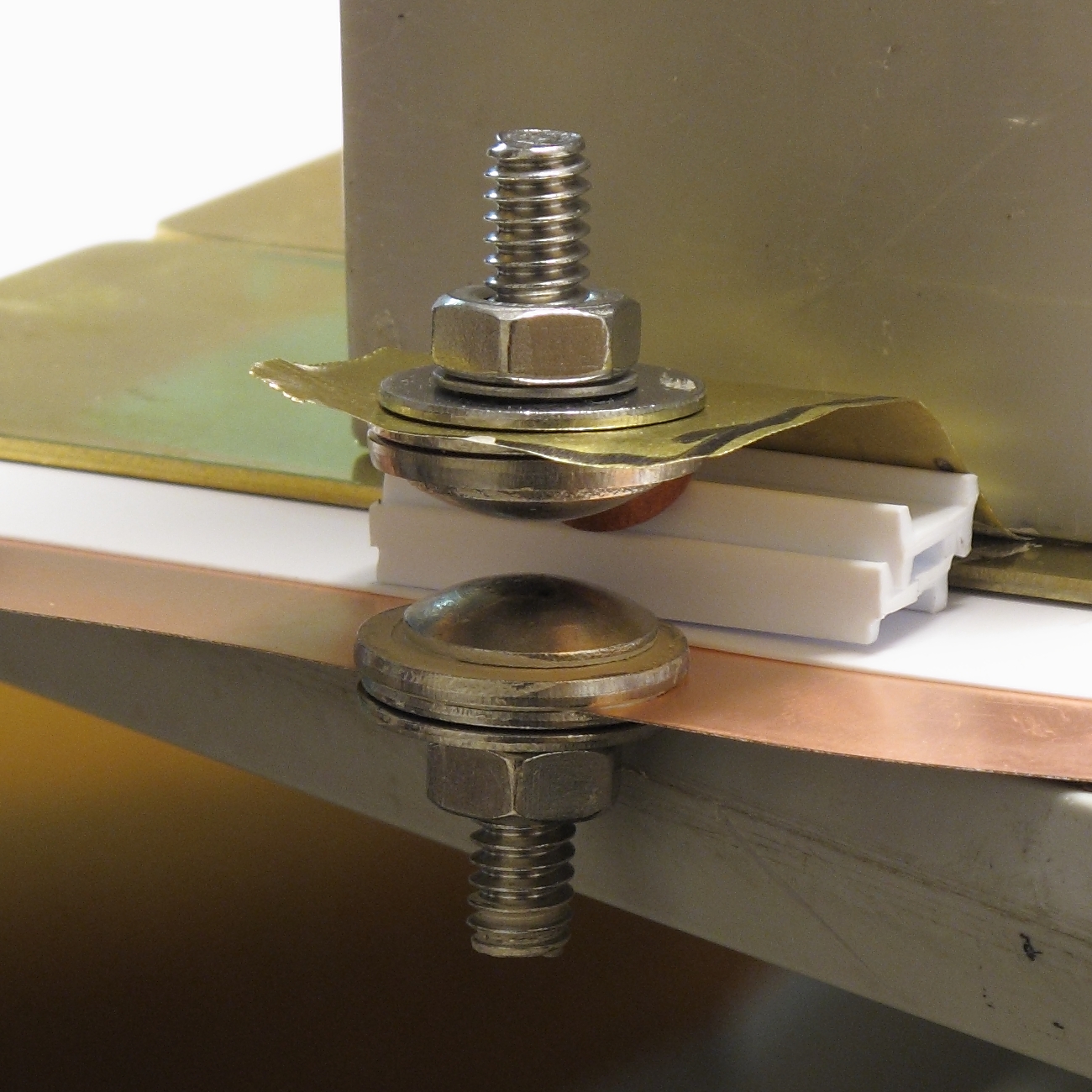
Figure 24: A faster and more stable spark gap design
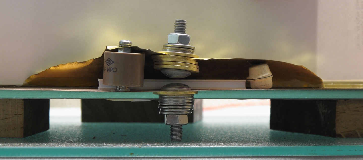
Figure 25: Revised spark gap design
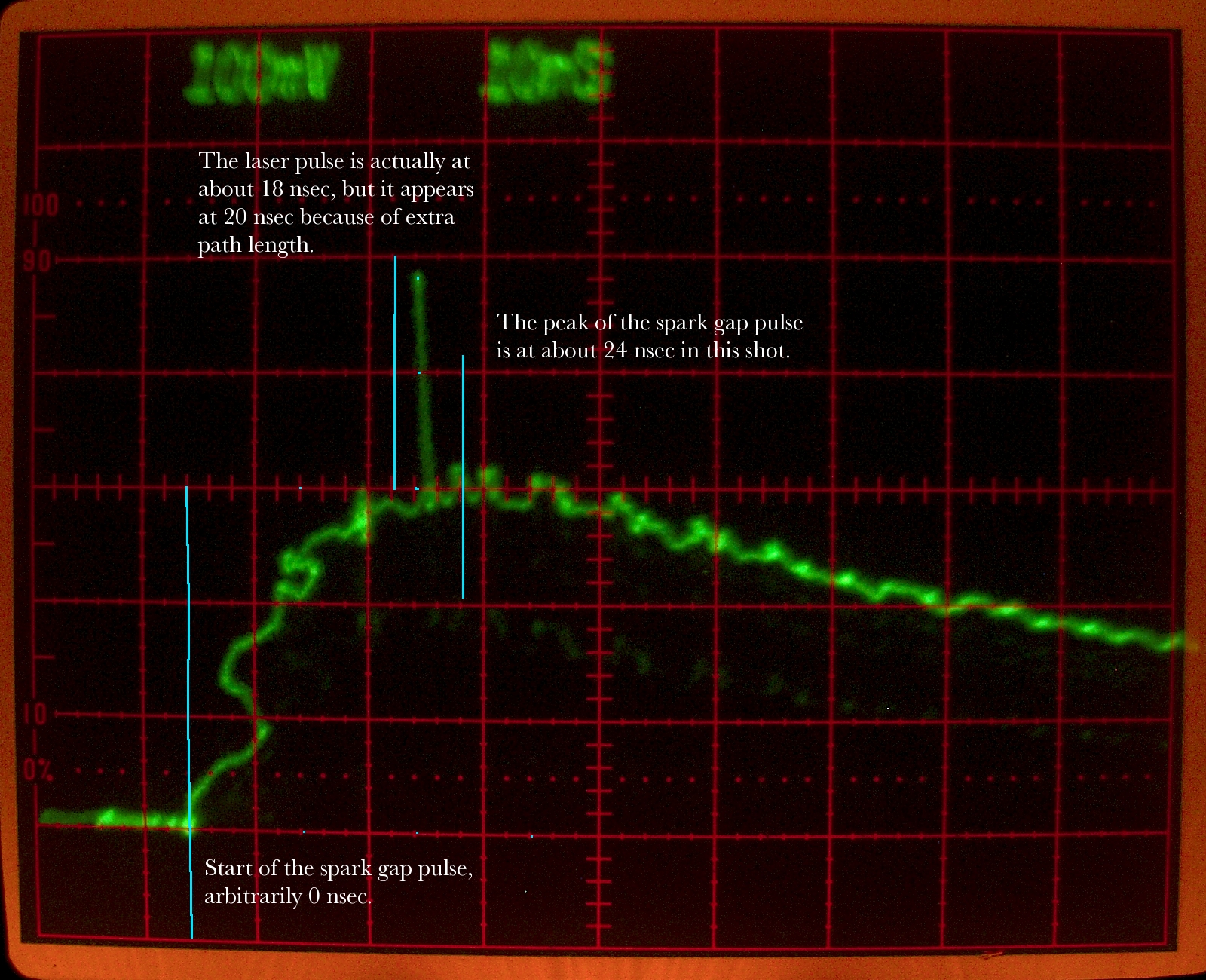
Figure 26: Scope trace, showing the laser pulse and the light from the spark gap
Special Note:
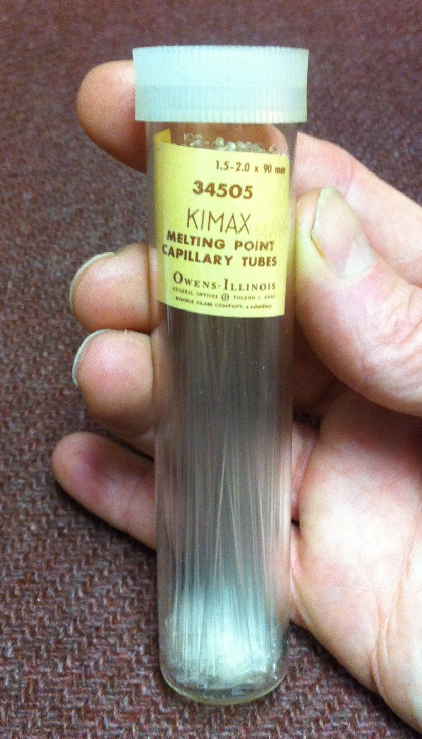
Figure 27: Capillary tubes
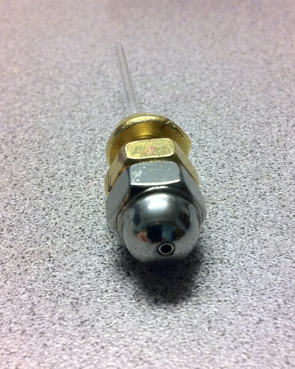
Figure 28: Triggered spark gap, head end
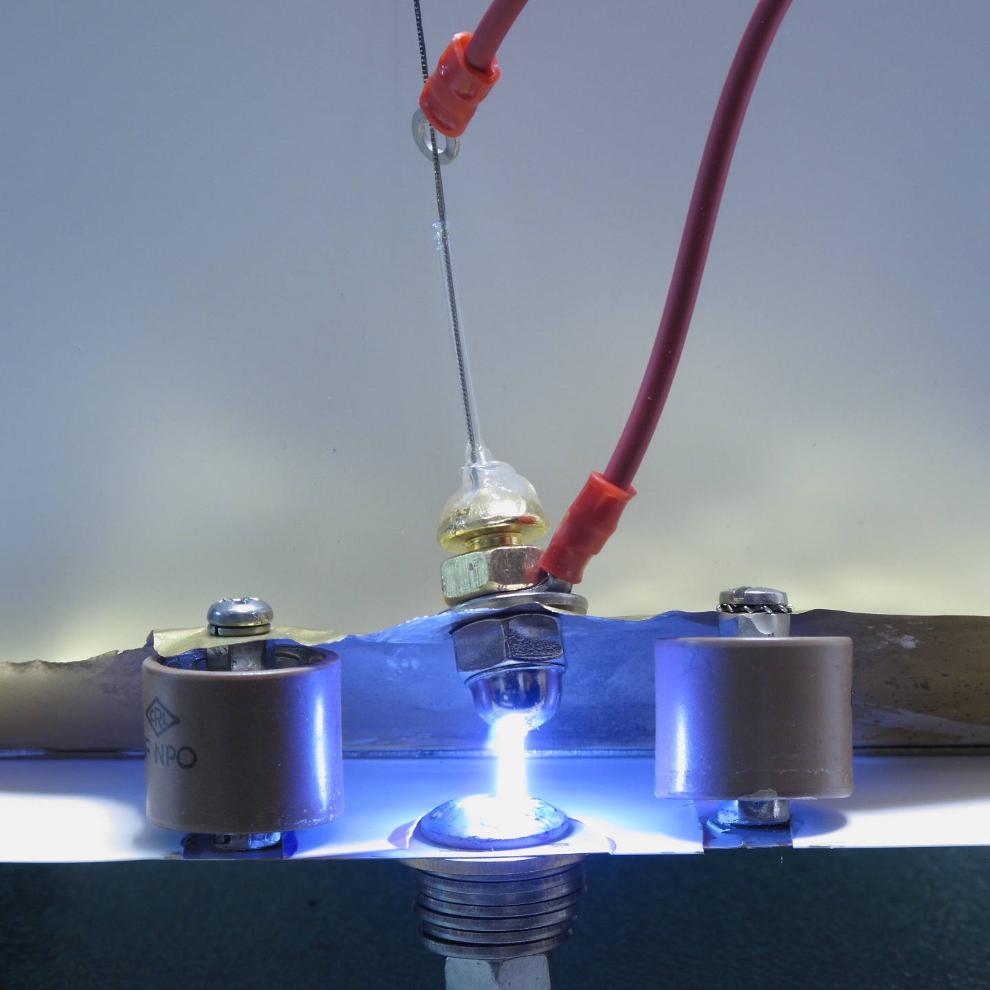
Figure 29: Triggered spark gap
Alternative Drive Circuits
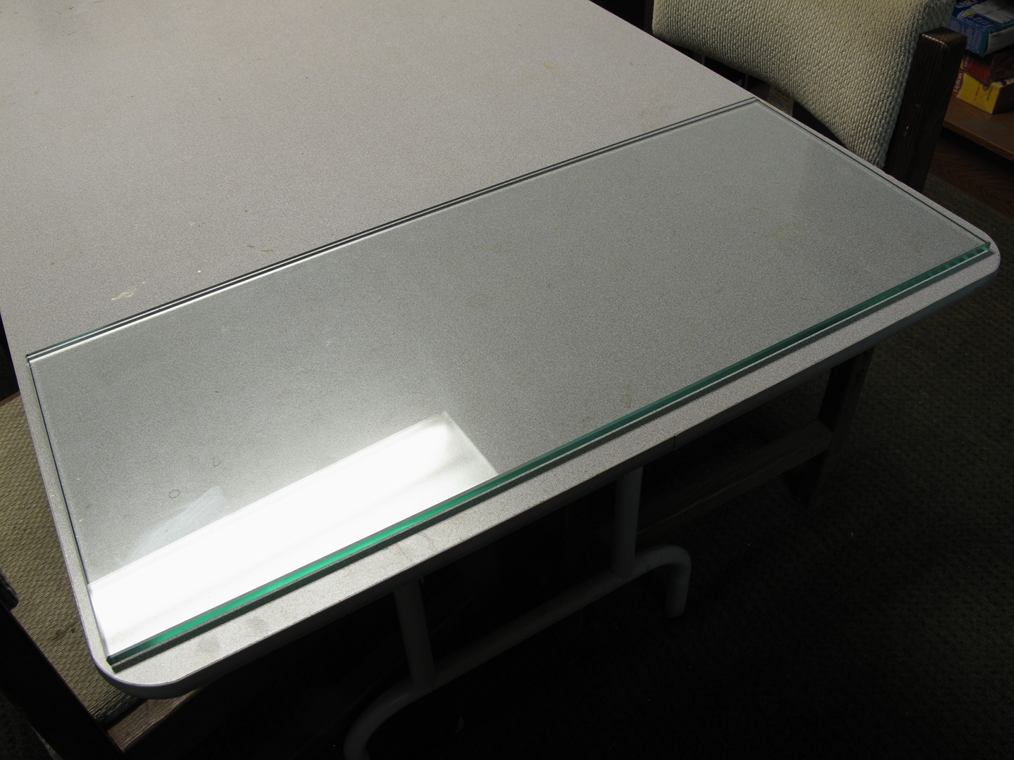
Glass plate in position

Baseplane in position on the glass
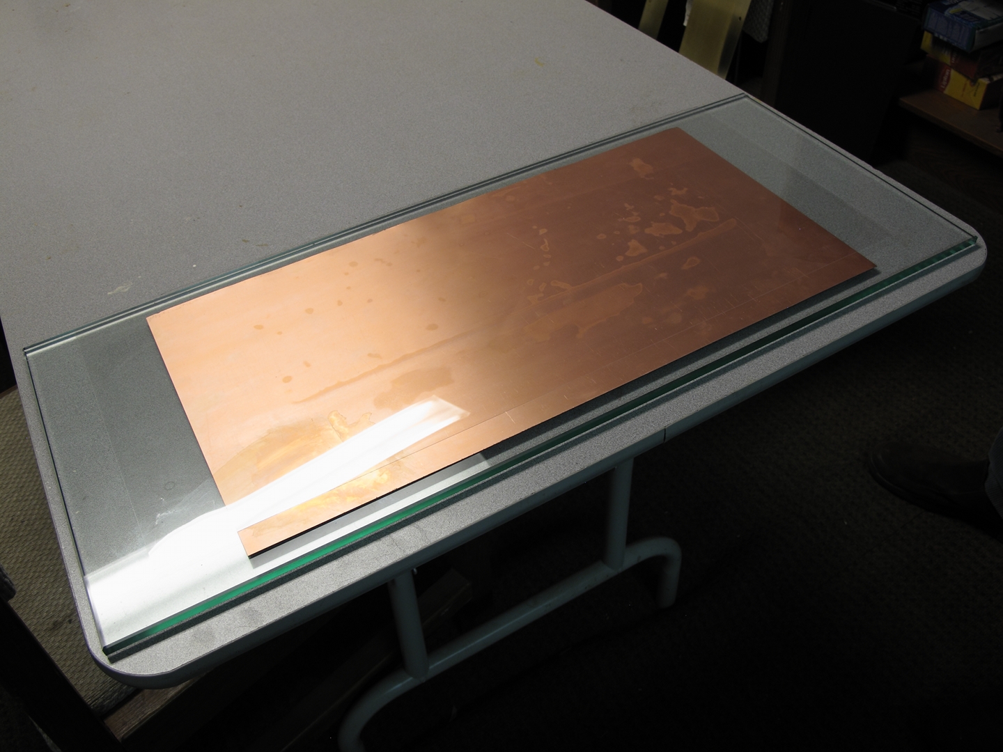
5-mil polyester sheet (the dielectric) on the baseplane
(See remark, just after Figure 40.)
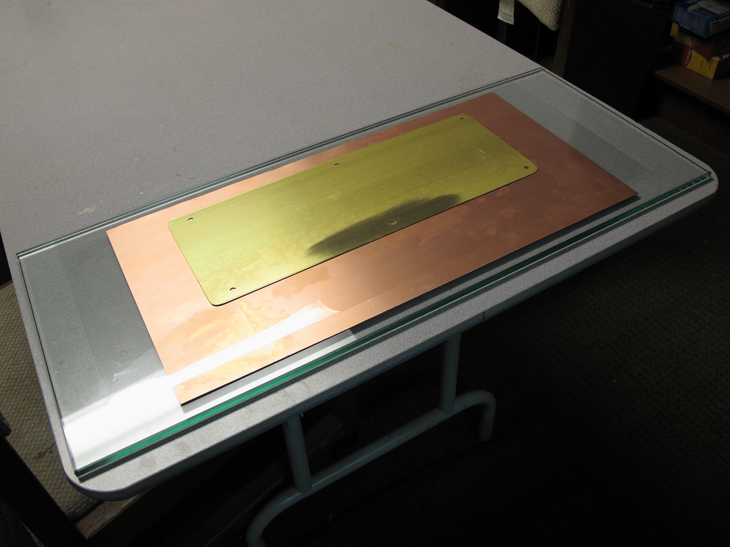
Upper plate of the dumper cap in place
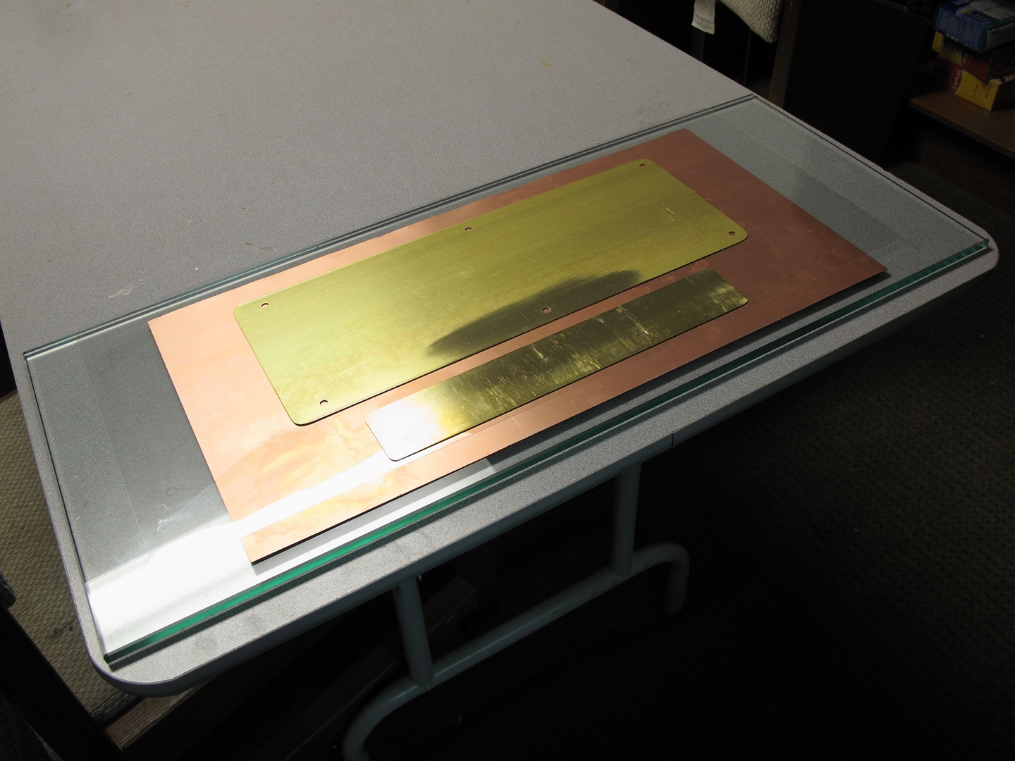
Upper plate of the peaker cap in place

Ground connection in place
Upper side of spark gap, shown in position
Channel electrodes in place
Weights in place
The laser, in operation
Figures 30-39: Assembling a Charge-Transfer version of the laser
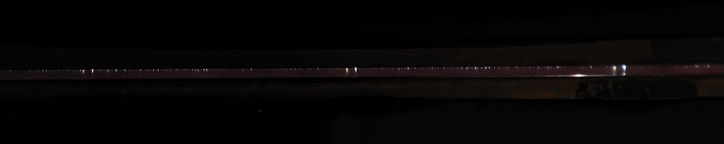
Figure 40: Channel of the Charge-Transfer version
Relevant Milestones
In closing:
Addendum:
Dye Lasers as Indicators of Performance
 br>
br>
Figures 41 & 42: Unfocused output driving a small dye laser
Figures 43 & 44: Fluorescent plastic sheet, lasing
Figures 45 & 46: Improved plastic sheet
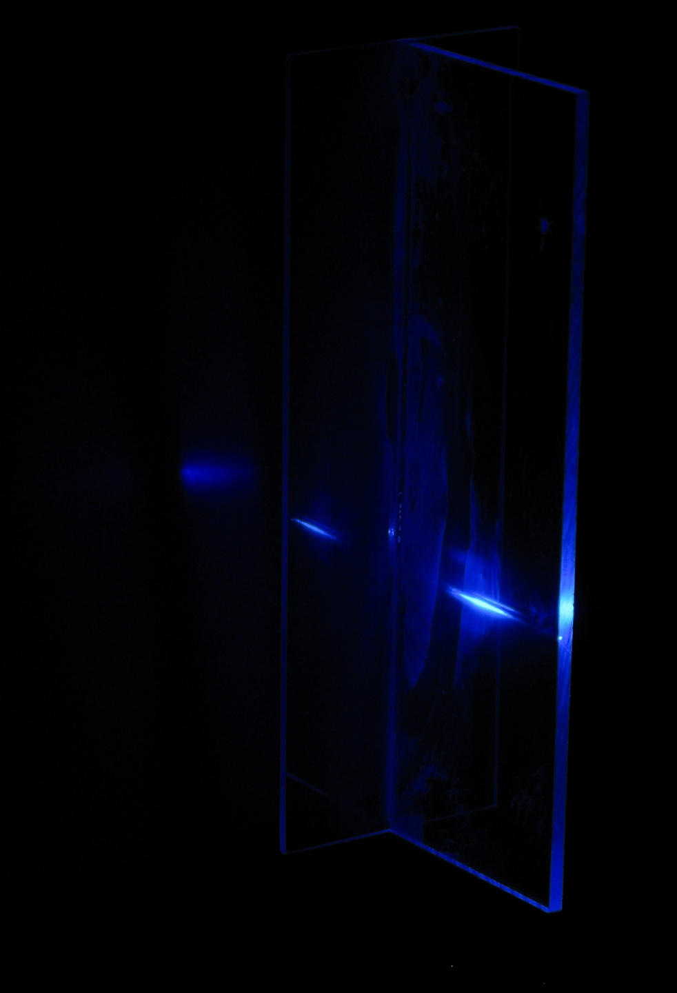
Figure 47: Improved plastic sheet, lasing
Figures 48 & 49: Plastic sheet with 2 slides
Acknowledgements
Links
There are various DIY laser projects on the Web, including several TEA nitrogen lasers. No two of these are alike, which underscores the fact that there are lots of ways to think about the requirements and parameters of these lasers.
This work is supported by
the Joss Research Institute
19 Main St.
Laurel MD 20707-4303 USA
Contact Information: