Please note: this preliminary version is, as of early
May, 2011, only just begun, and is extremely incomplete
and disordered. If you want further references or you
want to ask a question, you will find my email address
at the bottom of the page.
The nitrogen laser was discovered in 1963. As far as I can recall, it was the first ultraviolet gas laser, the first pulsed ultraviolet laser, and possibly the first-ever ultraviolet laser. It puts out short pulses of light at a wavelength of about 337.1 nm, a little shorter than the wavelength of an ordinary “blacklight” but not quite short enough to be described as “midwave UV”. This light is not visible, and it is even more dangerous than the light from small visible lasers. In addition, the laser operates on high voltage, so you should ONLY attempt to built it if you are prepared to exercise appropriate safety precautions. (I will list a number of these as we proceed.)
The nitrogen laser has very high gain. Excited nitrogen gas amplifies so well, in fact, that nitrogen lasers can usually operate without any mirrors at all, though especially with low-pressure ones it is common to use only a single mirror. (Using a mirror at one end of the laser lets you get all of the output at the other end, instead of having it divided between the two ends. With TEA nitrogen lasers there is another way to accomplish this, which I discuss in one of the videos.)
[Note: There are a few people who claim that the lack of mirrors means that a nitrogen isn’t a real laser, because it doesn’t involve a Fabry-Perot resonant cavity. That view is defective in two ways. First, the word LASER is an acronym that stands for “Light Amplification by Stimulated Emission of Radiation”, in this case, optical radiation: photons; there are also masers, which amplify microwaves rather than light. Neither version of the acronym includes any mention of resonant cavities, and any claim that a resonant cavity is necessary (for whatever mysterious reason) is ridiculous on the face of it. It is generally acknowledged, in fact, that there are quite a few naturally-occurring masers in outer space, which obviously do not involve resonant cavities. In addition, it is entirely possible to build a nitrogen laser that operates inside a resonant cavity; it just doesn’t happen to be necessary.]
Every laser must be “pumped”. That is, energy must be provided to it in an appropriate form. Some lasers are optically pumped. This can be accomplished with flashlamps, arc lamps, other lasers, other kinds of lamps including incandescent lamps, or even the sun. Others are driven directly by electricity. There are even a few chemical lasers. It all depends on the active material and its requirements, and on various other criteria that we aren’t going to get into here because there is neither space nor time. (If you are interested, there are various resources on the Web. I will link to some of these at the bottom of the page.)
All or nearly all nitrogen lasers are pumped by
electrical discharge, usually in fairly pure nitrogen
gas; but a nitrogen laser can even operate with air as
its active medium, and that is what we will start with.
I will note, however, that air is a lousy laser, and
that if you can get or produce nitrogen that contains
0.5% oxygen or less, you will get much better
performance. (I demonstrate the difference, using the
laser design on this page, in one or more of the videos.)
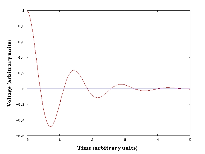
If you charge up a capacitor to some nominal voltage and then connect it to an inductor (a configuration that is often described as a “tank circuit” or, more formally, an L-C tank circuit), the voltage will change in a characteristic way. People who deal with electronics often say that such a circuit is “ringing”. Because all real circuit elements have some resistance, and because the circuit is radiating some of its energy into space, the oscillation decreases in amplitude with time.
Here is a simulation of what you might see on the screen of an oscilloscope if you had a modest amount of resistance in your circuit:

[If there is less resistance the ringing decays more slowly, and it goes on longer. There is a formal way to describe this characteristic, a so-called “Factor of Merit” of resonances, which is called Q in electronics. Very loosely speaking, the Q of a circuit is the number of times the voltage crosses the middle line of the diagram before the height (or depth) of each peak is less than about 1/3 of the height (or depth) of the first one. The Q of the resonance shown in the diagram above is somewhere around 3, which is low.]
A capacitor in this type of circuit can “ring down” to a negative voltage that is a large fraction of its initial charge voltage. This is termed “voltage reversal”; in the diagram, the reversal is 50%; a highly resonant circuit can achieve a reversal of well over 90%. [Just for reference, and for the sake of comparison: if you are building an organic dye laser that is pumped by light from a flashlamp, you want the Q of the circuit that drives the flashlamp to be a little less than 1. That is, you do not want any voltage reversal at all. There are several reasons for this, including the fact that many capacitors are damaged by reversal, especially at high voltages.]
If we position two capacitors so that there is only a narrow gap or channel between them, we can do something interesting with voltage reversal. First, we charge the two caps simultaneously, so that there is essentially no voltage across the channel. Then we short-circuit one of them. As it rings down, the voltage across the channel increases quite rapidly. In a design like the one I am using for this laser, it probably takes only a few dozen billionths of a second for the channel voltage to become larger than the initial charge voltage. (That is, at the time when the shorted capacitor rings down into negative voltage.)
In principle, the voltage difference between the two capacitors can easily get as high as about 1.9 times the initial charge voltage; but if we have designed and built the laser correctly, at some point a discharge will form in the channel. (If things are not quite right we will probably see white sparks instead of a nice even glow, and if the channel is too wide we may not see much of anything.)
Here is a schematic diagram of such a circuit, with a free-running spark gap as the switch:
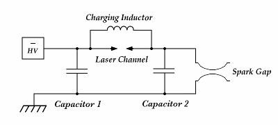
(You can click the small image if you want one with more pixels.)
I have shown the power supply with negative polarity here, but it is possible to operate the laser with either polarity. One way is quite likely to work better than the other, in fact, so you should try both. (My versions of this laser actually seem to work better with the positive output of the power supply connected to the laser channel, and the negative output connected to the ground plane.) I have shown a charging inductor in this diagram, but a resistor can also work.
This brings up another item: circuit topology. The topology of the versions I discuss on this page is probably best referred to as a “Voltage Doubler” circuit, though it does not actually double the voltage. (There doesn’t seem to be a better term.) Schematically, it looks like this:
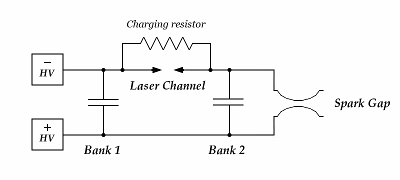
(I found that my lasers run better with positive polarity below and negative polarity above, so I have drawn the schematic diagram that way.)
The doubler circuit is one of two common topologies that people use for this kind of laser. The other is a “Charge-Transfer” circuit. In the course of exploring the design space, I constructed a CT version of the laser; it looks about like this:
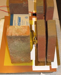
Here is the circuit diagram:
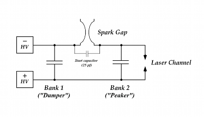
As you can see, one obvious change is that the switch and the laser channel have exchanged positions. With the doubler circuit, we charge both capacitors and then short one of them out; with this circuit, we charge one capacitor and then use it to charge the other one. The CT circuit is probably better suited to higher voltages, but this one performs adequately.
This design, btw, does not use a resistor across the laser channel. I originally thought a resistor would help by discharging the “Peaker” capacitor between shots, but Jarrod Kinsey suggested that I remove it, as he has found that his CT lasers work better without such a resistor. The operation of the laser improved when I did so, and I have omitted it from the schematic.
Let us, however, return to the voltage-doubling laser for now.
Assuming that we have built things well, and a discharge does form, that discharge is going to excite some of the nitrogen molecules in the channel. In doing so, it will pump the laser. Once pumping begins, it takes some time (probably more than 10 billionths of a second) before enough of the nitrogen molecules are excited that lasing can start. (This is important! Lasing does not begin at “the instant” that the channel starts to conduct. In fact, there isn’t any such “instant” — all of these processes take a certain amount of time, and in Physics a billionth of a second is quite a while. The laser we are building here puts out a light pulse that is less than 1 billionth of a second long if you measure its duration at half of its peak power, but that is not regarded as a particularly short laser pulse.)
[There is, among the projects in the Amateur Scientist
column, a low-pressure nitrogen laser project. It’s
quite a decent laser, all things considered. Unfortunately,
the description of how it works is very badly flawed. I
have written a Web page that is devoted to debunking and
correcting that description. If you are interested, you
will find a link to it in the references, below or on
the page on which I describe a TEA nitrogen laser as a project.]
(Although it is somewhat peripheral, you may want to read my rant on the Scientific American “Amateur Scientist” nitrogen laser. There are some potentially useful references at the end.)
There are various DIY laser projects on the Web, including several TEA nitrogen lasers. These will show you a variety of ways to think about the requirements and parameters of this laser type, as they are no two entirely alike.
Jarrod Kinsey has pointed me to a splendid page about homebrew TEA nitrogen lasers, written by Nyle Steiner. The design is perhaps even easier to construct than the ones on this page.
===============================================
Thomas Rapp, in Germany, has an excellent pageset about the lasers he has built. To get to the TEA nitrogen lasers, go to the list on the left side of the page, click “Stickstofflaser”, then click “TEA Laser”. His other lasers are just as interesting. [If you don’t read German, you can always use one of the translation utilities on the Web.]
===============================================
Hubert Pissavin has a TEA nitrogen laser that uses air as its lasant. His project is a good one: easy to build, and not expensive.
===============================================
The TEA nitrogen lasers of Alfonso Torres Rodríguez are more complex and more difficult than the one I present here, and they operate at higher voltages. Their performance is admirable — Alfon can run a dye laser at a distance of more than 50 cm with the unfocused beam of any of his better machines with air in the channel. [If you don’t read Spanish, you can always use one of the translation utilities on the Web.]
Alfon also has a number of YouTube videos showing his lasers in operation.
===============================================
Sam’s Laser FAQ
is an incredible resource, covering a tremendous variety
of laser types. My one caveat is that in addition to a
lot of important information there are many opinions,
some of which are more credible than others. When you
see descriptions of a laser or a project, or
specifications of a commercial device, they are
generally quite reliable; when you see someone stating
that dye lasers are not worth the trouble (because he
barely managed to threshold Rhodamine 6G with 200 joules
into his flashlamp), that’s not necessarily as
reliable. (It is entirely possible to threshold some
dyes
with just a few joules into a flashlamp,
but it is extremely difficult to threshold R6G or any
other dye if you drive your flashlamp with capacitors
that are not well adapted to fast-pulse service. This
clearly includes photoflash capacitors, though they are
admirably suited to slow pulse service.)
Email: a@b.com, where you can replace a with my first name (jon, only 3 letters, no “h”) and b with joss.
Phone: +1 240 604 4495.
Last modified: Tue May 9 12:28:54 EDT 2017