TJIIRRS: Number 21
DIY Spark Gaps for High Voltage Switching
(02 June, 2011, ff)
People have been using spark gaps to switch high voltages for hundreds of years. They provide good performance in a number of applications, including various kinds of laser. It is quite easy to build free-running (passive) spark gaps, and fairly easy to build small- to mid-size triggered gaps.
This page discusses a few simple gap designs. I also
hope to include a design for a DIY trigger unit, because
the requirements for triggering can be a bit tweaky and
because commercial trigger units are often expensive.
!! WARNING !!
If you operate an open spark gap, you need to be aware that it will destroy your hearing unless you use adequate ear protection. I strongly suggest a pair of earmuffs of the type used by people at rifle and pistol ranges, and it is sometimes a good idea to use earplugs in addition to the muffs. An open spark gap will also give you a nasty headache if you run it for a while and you don’t have hearing protection in place, but that’s strictly a secondary issue.
My hearing protector cost me about 35 dollars, and was well worth the price. It looks like this:
1: Untriggered (Free-Running or Passive) Gaps
Originally, a spark gap consisted of two rounded metal knobs on the ends of metal rods. These were often made of brass. No effort was made to minimize inductance, largely because nobody knew there was any such thing. As far as I’m aware no effort was made to control the switching except by changing the distance between the knobs.
Here is an example, from the Niagara Science Museum.
In some cases, this approach is more than adequate, and I doubt that I need to provide any more information than you can get from the photo, though you do want to be aware of the fact that wood has some conductivity at high voltages, which will have an effect on performance if you use it as a construction material. If this is a problem, there are various types of plastic that will work.
With many types of laser, however, switching speed
becomes more of an issue. Flashlamp-pumped dye lasers,
for example, are typically operated with pulses that
last anywhere from a few hundred nanoseconds to a
microsecond or two. Low-pressure nitrogen lasers are
more demanding; once the laser reaches threshold, it
rarely operates for more than about a dozen nanoseconds.
Atmospheric pressure nitrogen lasers are still tougher:
after the laser reaches threshold, lasing goes on for
only about one nanosecond, and any electrical energy
that is dissipated in the laser channel after that
single billionth of a second is wasted.
[Side note: it takes some time for a
discharge-driven laser to reach threshold after the
discharge in the laser channel (or flashlamp) begins to
form, a fact that many people (even a few laser
researchers) either don’t know about or tend to
forget. With nitrogen lasers, especially room-pressure
N2 lasers, the time to reach threshold is
almost invariably longer than the duration of the laser
pulse.]
Even a fairly simple spark gap, like the one at the right side of this photo, which is just a pair of lugnut covers intended for an 18-wheeler, can function quite well. This gap is being used to switch a room-pressure nitrogen laser, which (as I mention above) has requirements that are, in DIY terms, relatively stringent. [The laser and gap were designed and built by Jarrod Kinsey.]
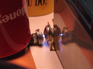
I tend to make gaps of this general type from carriage bolts, which are available at hardware stores. Here is an example:
[The red mug is being used as a weight, to help maintain good contact between the electrode on the left side and the baseplane of the laser. Note that I’ve mounted the other electrode on a piece of brass shim stock. The wide current path helps keep the inductance down; a wire would not work well in this application, which is another room-pressure nitrogen laser. The bolts here, btw, are ¼-20 NC carriage bolts, a convenient size that is readily available and can handle the modest energies and currents involved in these lasers.]
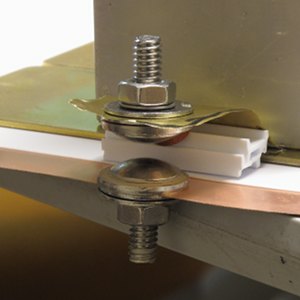
Here is an improved version:
(Instead of sitting the lower electrode on top of the baseplane and holding it down with a weight, I have mounted it in a hole in the baseplane. This helps decrease the inductance, and probably provides better electrical conductivity.)
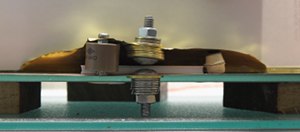
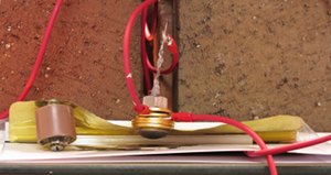
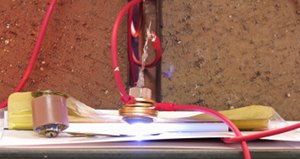
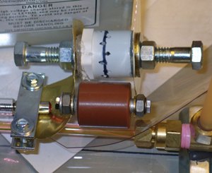
Spark gaps take some time to initiate, and it can help if you push a modest amount of current through them as quickly as possible; this is easily accomplished by placing a [relatively] small capacitance across the gap, and positioning it electrically and physically close. Here is a further refinement of the gap from the photo above:
The capacitor (which in this case is 25 pf; I rarely use anything over 200 pf as a “start cap”) is the brown cylinder, a little to the left of the gap. I have provided room for it by using a wider piece of shim stock.
Although these designs certainly work, they are not
intended as cookbook recipes. They are, rather, general
notions intended primarily as food for thought.
2: A Straightforward Triggered Gap Design
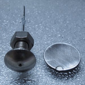
There are several ways to configure a triggered gap. The most common of these is often referred to as a “trigatron”. It has a trigger electrode in the center of one of the main electrodes, and is separated from it by an insulator. Here are the parts of one of mine:
I made this gap by drilling a hole down the axis of a carriage bolt; I used a glass tube as the insulator, and a broken piece of jeweler’s saw blade as the trigger electrode. These items are held in place with silicone rubber caulk, to give them a bit of flexibility.
The tube is a melting-point capillary. (I had bought a bunch of these on eBay, for use in a different laser project, and had quite a few left over.) A hematocrit capillary, which is very similar, should work just as well. This type of tube has one sealed end, which I cut off by scribing the glass (gently — it’s very thin, and quite delicate) with the edge of a ceramic integrated circuit package, and pulling on the ends of the tube. (Protect your hands and eyes!)
The flat disk to the right of the triggered electrode is a knockout from an electrical box, which I have sanded to expose clean metal surface. You would ordinarily use another convex shape for the opposing electrode, as I did in the free-running gaps; but in some cases, particularly at lower voltages, a flat works about as well. This gap runs nicely at 12 kV. Here it is, installed on a TEA (room pressure) nitrogen laser:
Because of the way this particular laser is constructed, the gap doesn’t actually need a start capacitor; but I have added one anyway, on a “just-in-case” basis. (The laser is a slightly unusual design; if you are interested, please see the page I’m writing about it.)
So far, as mentioned above, I have constructed these gaps from ¼-20 NC carriage bolts. If you are storing more than a few joules in your capacitors, however, you probably want to use larger bolts if you decide to go with this design.
(As with the free-running gaps, this is not intended as a cookbook; there are many ways to design and build trigatrons.)
2A: Moving to Higher Power
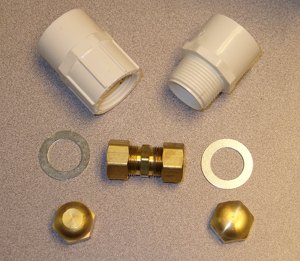
If you have access to a machine shop, you can easily build larger gaps. Brass bar stock is available in many places, and you can shape it as necessary. You can also create a longer path on the inside or outside of a plastic housing (to decrease the chances of an arcover), possibly even by simply cutting deep threads into it. Alternatively, if you have access to machine tools you can suit the sizes of your electrodes to fit available commercial plastic pieces. (PVC plumbing is your friend here. Just don’t get it too hot — it apparently emits truly noxious gases when overheated.)
You can trigger a midsize to large gap with a spark plug. I have used a lawnmower plug on a mid-sized gap with some success. You will need to remove the hooked prong from the plug, which is not easy (these things are made to stand up to millions of operations, at high temperatures!), and you will want to choose a plug with a center electrode that is as well centered as possible — many of them are quite badly off-center. (If the center electrode is not in the center it requires a larger hole in the adjacent electrode that surrounds it, and it will always or nearly always strike to the nearest edge of that hole, which will eventually erode the electrode unevenly.)
Particularly for operation at high voltages, you will almost certainly need to shape the electrodes carefully, to minimize corona losses and arcovers. There are various mathematical profiles that people have used, which you can find on the Web. You can approximate one of these by eye if your application is not particularly crucial, but I presume that if you have access to CNC machine tools you can program in the curve you want.
One advantage of going to a machined device is that it
becomes much easier to pressurize it, should you want to
do so. A pressurized gap can be used at higher voltage
than a room-pressure gap with the same spacing, and it
is also possible to control some of the characteristics
by tweaking the gas mixture. I believe that CO2
or a mixture of CO2 and N2 is a
good (or at least common) choice, but you should check
that before you believe it.
3: Triggering Requirements for Trigatrons
Although I have not [yet] investigated this issue myself, I will note that the old EG&G literature for their commercial trigatrons (which are very good gaps) suggests that the trigger pulse should have risetime of less than one μsec. Their preferred configuration has the positive-going output of the trigger generator connected to the trigger electrode and the negative-going output connected to what they refer to as the “adjacent” electrode. The adjacent electrode is positively charged, and the opposite electrode is negatively charged. Here is a diagram:
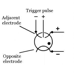
It is probably possible to apply the negative-going
trigger pulse to the opposite electrode, but it
certainly isn’t necessary, and it would require
significantly higher trigger voltage.
4: Enclosures
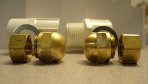
As mentioned above, an open gap generates a nasty shockwave. It is possible to put an enclosure around a spark gap, which significantly lowers the acoustic pressure that it generates, but there is an issue that you need to be aware of: a spark will travel much farther along a surface than through air or other gas, so you have to provide a significantly longer path on both the inside and the outside of the enclosure in order to prevent flashovers. Here is how I built the passive gap for a Marx generator that powered a small flashlamp-pumped dye laser:
Obviously, what you see in these photos is only one of many ways in which you can do this.
Notice, btw, that I drilled holes in the PVC enclosure
to permit some air circulation. This helps control heat,
which can be an issue if you fire the gap often. (The
EG&G gaps mentioned above are in ceramic enclosures,
and are pressurized, so they are not vented.)
5: Field-Distortion Gaps
(A Brief Glimpse)
There is another way to trigger a spark gap. It is referred to as “field distortion”. To trigger a gap this way, you use a trigger electrode, typically in the shape of a ring, that is positioned between the two main electrodes. Resistors equalize the voltages, so that when the gap is energized the trigger electrode is held at a voltage between the voltages of the main electrodes. (Assuming that the lower electrode is at ground and the upper one is “hot”, if the trigger electrode is midway between them it gets half the voltage that is on the upper electrode. If it is 1/3 of the way from the lower to the upper, it gets 1/3 of the voltage. I believe that these are the most common positions.)
To trigger the gap, you apply a fast-rising pulse to the trigger electrode. This distorts the electric field between the main electrodes, hence the name. Unfortunately for the DIYer, it is not necessarily very easy to generate a pulse that rises rapidly enough to trigger such a gap. A so-called “spiral generator” or “spiral vector generator” is probably a good trigger source, but such devices are, themselves, difficult to trigger.
I may be looking into this, and if I get anywhere I will report my results here. Meanwhile, here is a page with diagrams of a field-distortion gap designed by Bill Lemieux, and here is a photo of the completed gap.
Properly operated field-distortion gaps should, if I
understand correctly, switch faster and with better
pulse-to-pulse uniformity than trigatron gaps, which
are, in turn, faster and more uniform than free-running
passive gaps.
6: A Note on Really High Speed Gaps
By using extremely low-inductance connections and very tight gap spacing (about 0.1 millimeter), with water as the dielectric in the gap instead of a gas, it is possible to make a switch that closes in as little as 1 or 2 nsec. This, however, is not at all trivial; and such a switch can only be used with pulsed charging, because water will only hold off high voltage for a few hundred nsec. Moreover, only extremely pure water will work for this at all; twice-distilled water is only just adequate, and deionized water is preferable.
Reference:
“Water spark gap for a nitrogen laser”
Seishiro Saikan and Fujio Shimizu
Review of Scientific Instruments, volume 46 number 12
(December, 1975), pages 1700 & 1701
Some things to note about this — first: when they
filled the gap with air (and opened up the spacing to
3.5 mm so it would fire at a similar voltage), the
risetime they measured was 15 nsec. That’s
probably about 30% faster than the best of the gaps I
describe above. This is not particularly surprising
— their gap is a very low-inductance design. Second:
even one nsec is far too slow to match the
description and diagrams of the Scientific American
“Amateur Scientist” nitrogen laser. That
description is plain hogwash.
the Joss Research Institute
19 Main Street
Laurel MD 20707-4303 USA
Contact Information:
My email address is a@b.com, where a is my first name (just jon, only 3 letters, no “h”), and b is joss.
My phone number is +1 240 604 4495.
Last modified: Thu Jun 23 16:06:29 CDT 2016

